Implementing Text mode for a VGA controller in Verilog
After having written about implementing a VGA controller in Verilog I wanted to improve it with a new functionality: the Text mode.
Single stepping an ATmega with a FPGA
As continuation of the post about the internals of the clock of an ATMega, I decided to test the possibilities of simulating a clock using a FPGA, in particular using my loyal mojo development board.
My intent is to create a system to generate glitching with an external clock, but since I like to proceed one step at times I start creating a 16MHz clock that can be switched to a manual pulse to create a single step atmega.
Resurrect an old vulnerability: CVE-2014-4699
With this post I want to accomplish a few objectives:
- reproduce a vulnerability
- debug a running kernel
- improve a proof of concept and make it more reliable
Studying ATMega's clock
As any computing device based on transistors and flip-flop, a microcontroller needs a clock to give the "rythm" for the cpu and peripherals. In particular for the ATMega328p the clock distribution is the following
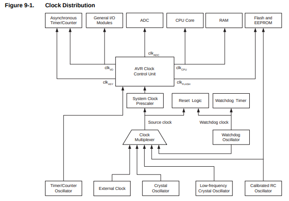
(for more information look at the datasheet).
Here I describe the ATMega328p but a lot of informations are valid for other microcontrollers of the same family and for some aspects also for any kind of microcontroller.
Available options
This device allows for different sources as clock, the selection is
done by setting the fuse bits CKSEL 3..0
Fuse CKSEL3..0
|
Note | |
|---|---|---|
| Low power cystal oscillator | 1111 - 1000 | typical configuration for an Arduino, it gives the lowest power consumption, but is not capable of driving other clock inputs, and may be more susceptible to noise in noisy environments |
| Full swing cystal oscillator | 0111 - 0110 | the crystal oscillates along the power rail, it is useful for driving other clock inputs and in noisy environments. It has high current consumption. Note that it will only operate for VCC = 2.7 - 5.5 volts |
| Low frequency cystal oscillator | 0101 - 0100 | optimized for use with a 32.768kHz watch crystal |
| Calibrated internal RC oscillator | 0010 | provides an approximate 8.0MHz clock, it's voltage and temperature dependent but can be user calibrated |
| External clock | 0000 |
Note that the CKSEL0 and SUT1..0 bits configure the startup time, i.e.
the number of stable clock cycles needed to successfully start-up the device.
Just as reminder, these are all bits from the low fuse:
| CKDIV8 | CKOUT | SUT1 | SUT0 | CKSEL3 | CKSEL2 | CKSEL1 | CKSEL0 |
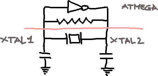
For all but internal RC oscillator the pin to use to connect the oscillator
are XTAL1 and XTAL2 (pin PB6 and PB7 respectively). They
are the input and output of an inverting amplifier which can be configured
for use as an On-chip oscillator; but what does it mean?
On-Chip oscillator
Following the Application Note 118 about CMOS Oscillators
we know that using an odd number of NOT gates we can create the following
circuit
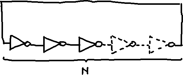
that generates a clock with frequency
$$ f = {1\over 2nT_p} $$
where \(T_p\) is the propagation delay for gate.
In the same application note is indicated the schematics for a crystal oscillator that I think is the same internal circuitery used into the ATMega for the on-chip oscillator that I imagine like this
Reading the clock signal
For a future project I want to know the electrical characteristics of the clock signal used in an arduino, but if I connect directly the probe with the pins the system stops to work probably because this process alters the capacitance of the on-chip oscillator and make this unusable. Indeed in the datasheet are indicated with precision the values of capacitance that are needed to make the crystal oscillate correctly (tipically 22pF).
To allow a probe to read a signal from the oscillator I need a buffer, i.e. a circuit
that isolate the oscillator from the probe. In my setup for
this experiment I used a BUF634 with a
+-5V as power supply and its input connected to the XTAL2 pin. Obviously the output
is connected with my oscilloscope's probe.
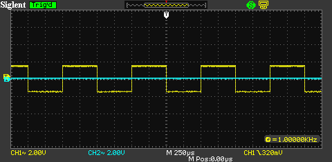
The signal as seen from my oscilloscope screen is
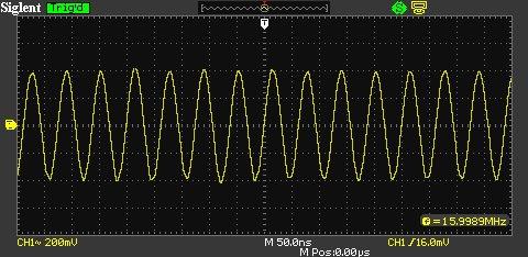
(this is dumped using the script described in another post)
At this point I can read a signal of a little less than 1 Volt (in the image above the signal
is symmetric with respect to the zero value but this happens because I use the AC coupling,
in reality is all positive).
Getting started to reverse AVR code
First of all, the instructions used on ATMel's chips are RISC-like, aligned to 2-byte addresses but with instructions that can be 16 or 32-bit long.
Registers
The registers have all 8-bit size.
-
pcis the program counter, cannot be modified directly. Since the instructions are all two bytes longs (a word), the value inside this register is an index of words. -
xstands forr27:r26 -
ystands forr29:r28also is the frame pointer -
zstands forr31:r30and is used as argument foreicall -
r0tor25are general purpose registers, used also for calling subroutines (see below the section about calling conventions).
What is missing from this list is the stack pointer: it's not a directly accessible
register, it's implemented using the memory address couple 0x3e:0x3d, see the section about
the prologue of a function to see what this means.
Note: for avr-libc r0 and r1 are particular registers that have fixed meaning,
in particular:
-
r0is a temporary register -
r1is usually zero
Harvard architecture
Unlike well known systems, this architecture has the memory space separated from the code space: the first is called SRAM, the second Program.
For this reason there are separated instructions to load and to store
data in these spaces, lds/sts and lpm/spm respectively.
Another particularity is that by the memory space can be accessed some peripherics
SRAM
Program
Arithmetic
It's important to understand how mathematics works with registers: the first thing to learn is that (in all the architecture) the arithmetic is module the number of bits; the other thing is that negative numbers are implemented via two's complement. I have a post dedicated to that.
Flags
As the registers have a fixed size, arithmetic operations can overflow, for example
think of the result of the sum of two register containing each the value 0xff,
the result, 0x1fe, cannot fit into the destination register. For this reason
exists a special register named sreg containing a bit (called flag)
indicating when a overflow happened.
It's not the only flag dedicated in this register, the list is
| Flag | Description |
|---|---|
| C | there is an overflow |
| Z | Zero flag |
| N | Negative flag |
| V | two's complement overflow |
| S | \(N\oplus V\) |
| H | half carry |
| T | transfer bit |
| I | global interrupt flag |
Calling convention
The processor doesn't have a notion of argument of its own, when you call a routine in your program the caller have to define a convention with the callee in order to communicate. Usually is set by the compiler (I'm not completely sure).
Using avr-gcc we have the following indications (source):
- An argument is passed either completely in registers or completely in memory.
-
To find the register where a function argument is passed, initialize the register number Rn with R26 and follow this procedure:
- If the argument size is an odd number of bytes, round up the size to the next even number.
-
Subtract the rounded size from the register number Rn.
-
If the new Rn is at least R8 and the size of the object is non-zero, then the low-byte of the argument is passed in Rn. Subsequent bytes of the argument are passed in the subsequent registers, i.e. in increasing register numbers.
-
If the new register number Rn is smaller than R8 or the size of the argument is zero, the argument will be passed in memory.
-
If the current argument is passed in memory, stop the procedure: All subsequent arguments will also be passed in memory.
- If there are arguments left, goto 1. and proceed with the next argument.
- Return values with a size of 1 byte up to and including a size of 8 bytes will be returned in registers. Return values whose size is outside that range will be returned in memory.
- If a return value cannot be returned in registers, the caller will allocate stack space and pass the address as implicit first pointer argument to the callee. The callee will put the return value into the space provided by the caller.
- If the return value of a function is returned in registers, the same registers are used as if the value was the first parameter of a non-varargs function. For example, an 8-bit value is returned in R24 and an 32-bit value is returned R22...R25.
- Arguments of varargs functions are passed on the stack. This applies even to the named arguments.
Instruction sets
Here a summary of the instrutions available on this architecture, with a little description of the operations that they implement. To have more informations read the summary or the complete reference.
Arithmetic
| Instruction | Description |
|---|---|
| add ra, rb | adds two register and stores the result in the first one |
| adc ra, rb | adds two register using also the carry flag and stores the result in the first one |
| adiw ra, K | adds immediate to word |
| inc ra | increments a register by one |
| sub ra, rb | subtracts two registers and stores the result in the first one |
| sbc ra, rb | subtracts two registers using also the carry flag and stores the result in the first one |
| sbiw ra, K | subtracts immediate from word |
| dec ra | decrements a register |
| com ra | takes the one's complement of a register |
| neg ra | takes the two's complement |
| eor ra, rb | calculates the exclusive or of two register and stores the result in the first one |
| mul ra, rb | calculate the product between two registers and then place the result into r1:r0 |
Load and store
| Instruction | Description |
|---|---|
| ldi ra, K | loads immediate in register |
| lds ra, K | loads register with value stored in address |
| ld ra, x | loads register with value stored in address contained in x |
| ld ra, x+ | |
| ld ra, -x | |
| ldd ra, x+q | loads register with value stored in address pointed by x + q |
Branch
In AVR exists only two opcodes for branching, brbs <bit flag> <relative jump> and brbc <bit flag> relative jump>
that for easy of use have a few aliases
| Test | Boolean | Mnemonic | Complementary | Boolean | Mnemonic | Comment |
|---|---|---|---|---|---|---|
| Rd > Rr | Z & (N ^ V) = 0 | BRLT | Rd <= Rr | Z+(N ^ V) = 1 | BRGE | Signed |
| Rd >= Rr | (N ^ V) = 0 | BRGE | Rd < Rr | (N ^ V) = 1 | BRLT | Signed |
| Rd = Rr | Z=1 | BREQ | Rd != Rr | Z=0 | BRNE | Signed |
| Rd <= Rr | Z+(N ^ V) = 1 | BRGE | Rd > Rr | Z & (N ^ V) = 0 | BRLT | Signed |
| Rd < Rr | (N ^ V) = 1 | BRLT | Rd >= Rr | (N ^ V) = 0 | BRGE | Signed |
| Rd > Rr | C+Z=0 | BRLO | Rd <= Rr | C+Z=1 | BRSH | Unsigned |
| Rd >= Rr | C=0 | BRSH/BRCC | Rd < Rr | C=1 | BRLO/BRCS | Unsigned |
| Rd = Rr | Z=1 | BREQ | Rd != Rr | Z=0 | BRNE | Unsigned |
| Rd <= Rr | C+Z=1 | BRSH | Rd > Rr | C+Z=0 | BRLO | Unsigned |
| Rd < Rr | C=1 | BRLO/BRCS | Rd >= Rr | C=0 | BRSH/BRCC | Unsigned |
| Carry | C=1 | BRCS | No carry | C=0 | BRCC | Simple |
| Negative | N=1 | BRMI | Positive | N=0 | BRPL | Simple |
| Overflow | V=1 | BRVS | No overflow | V=0 | BRVC | Simple |
| Zero | Z=1 | BREQ | Not zero | Z=0 | BRNE | Simple |
| Instruction | Description |
|---|---|
| sbrs Rr | Skip if Bit in Register is Set |
| sbrc Rr | Skip if Bit in Register is Cleared |
Examples
Below take a look to some examples of common routines implemented with this language
Prologue
This is the start of a function, where it sets its frame pointer and allocate the space into the stack for local variables; generally looks like the following
push r28
push r29        ; save the frame pointer
in r28, 0x3d
in r29, 0x3e    ; set the frame pointer to the location of the stack pointer
subi r28, 0x10  ; reserve space in the stack for local variables
sbci r29, r1    ; (taking into account possible carry)
In this case the code saves the frame pointer of the caller and sets the frame pointer to the actual position of the stack pointer. The moves downs the frame pointer of 16 bytes to create space for the local variables. I think is backward with respect to the normal use of stack and frame pointers in the x86 code.
To access local variables you simply can use the load/store with displacement instruction with the
y register (that is the frame pointer)
ldd r24, y+1
ldd r25: y+2
eor r24, r25
ld r25, r1
std y+1, r24
std y+2, r25
strlen
    movw r30, r24
loop:
    ld r0, z+
    tst r0
    brne loop

    com r24
    com r25
    add r24, r30
    adc r25, r31
    ret
Here the tricky part are the last five instructions (not ret of course):
when the r0 contains a NULL byte then z point to the address of that byte
plus one (remember the post-increment addressing), so the com (the one's complement),
and add/adc instructions can be summarized as follow
$$ \eqalign{ r25:r24 &= r31:r30 + \left(r25:r24 \oplus {\tt 0xffff}\right)\cr &= r31:r30 - 1 + \left(r25:r24\oplus {\tt 0xffff} +1\right)\cr &= r31:r30 - 1 - r25:r24\cr &= \hbox{pointer to the next address fo the NULL byte} - 1 - \hbox{pointer to the start of the string}\cr &= \hbox{number of bytes not NULL} } $$
memcpy
    movw r30, r22
    movw r26, r24
    rjmp start
loop:
    ld r0, z+
    st x+, r0
start:
    subi r20, 0x01
    sbci r21, 0x00
    brcc loop
    ret
Sign extension
This section explains how I arrived to understand the meaning of this piece of code:
lds r24, y+1
lds r25, y+2
mov r0, r25
lsl r0
sbc r26, r26
sbc r27, r27
initialy didn't make any sense, it loads from the stack a short and then left-shifts the most significant byte; to end it subtracts two unrelated registers using the result of the shifting as carry.
Pratically r26 and r27 are always zero if the last bit of r25 is zero, if
it's not zero then r27:r26 are equal to 0xffff. Seems sign extension to me.
In order to prove my point I decided to experiment and to experiment I need to create a test case where I cast a variable from short to 32bits like the following:
$ cat extended.c
#include<stdint.h>

int32_t miao(short value) {
    return (int32_t)value;
}
$ avr-gcc -c extended.c
Once compiled I can look at the assembly code generated and bingo
$ r2 -A -a avr extended.o
[0x08000034]> pdf
/ (fcn) entry0 44
|   entry0 ();
|           0x08000034      cf93           push r28                    ; [01] m-r-x section size 44 named .text
|           0x08000036      df93           push r29
|           0x08000038      00d0           rcall 0x800003a
|           0x0800003a      cdb7           in r28, 0x3d                ; '=' ; IO SPL: Stack lower bits SP0-SP7
|           0x0800003c      deb7           in r29, 0x3e                ; '>' ; IO SPH: Stack higher bits SP8-SP10
|           0x0800003e      9a83           std y+2, r25
|           0x08000040      8983           std y+1, r24
|           0x08000042      8981           ldd r24, y+1
|           0x08000044      9a81           ldd r25, y+2
|           0x08000046      092e           mov r0, r25
|           0x08000048      000c           lsl r0
|           0x0800004a      aa0b           sbc r26, r26
|           0x0800004c      bb0b           sbc r27, r27
|           0x0800004e      682f           mov r22, r24
|           0x08000050      792f           mov r23, r25
|           0x08000052      8a2f           mov r24, r26
|           0x08000054      9b2f           mov r25, r27
|           0x08000056      0f90           pop r0
|           0x08000058      0f90           pop r0
|           0x0800005a      df91           pop r29
|           0x0800005c      cf91           pop r28
\           0x0800005e      0895           ret
UART communication
Like looking for printf() in "normal code", in embedded, bare-metal code
you probably are interested in finding where the system communicates with
the user, and in AVR systems this means the serial port.
The Atmel has produced a certain number of microcontrollers with a serial port, someone with more the one (but also a few without native support, where you need to bing bang some pins to recreate the functionality).
Explaining how the UART protocol works is out of scope of this post, you only
need to know that you need to specify the number of bits, and the speed of trasmission
of these and in a microcontroller this is done via some registers.
The most important registers are the following
UCSR0A |
|||||||
RXC0 |
TXC0 |
UDRE0 |
FE0 |
DOR0 |
UPE0 |
U2X0 |
MPCM0 |
UCSR0B |
|||||||
RXCIE0 |
TXCIE0 |
UDRIE0 |
RXEN0 |
TXEN0 |
UCSZ20 |
RXB80 |
TXB80 |
UCSR0C |
|||||||
UMSEL01 |
UMSEL00 |
UPM01 |
UPM00 |
USBS0 |
UCSZ01 |
UCSZ00 |
UCPOL0 |
obviously each register has an address (probably) different in different microcontrollers.
If you want a tutorial look here.
Sending command to an Anet A8 3d printer by the serial port with python
Since last year I have an Anet A8, a 3d printer received from China as a kit and that I use as you can expect to print 3d models and experiment with this technology.
In this post I want to describe a thing that is very simple but that is not (probably) well known: the board that manages the functionality of this device is (in the majority of the cases) an arduino-like system that receives commands via a serial port and acts accordingly enabling the various systems that compose the printer, like stepper motors, bed heater etc...
The commands understood by this sistem of boards is called Gcode, is a text based
language used primarly for movements in a 3d spaces; you can find a list of these commands
in the page of the RepRap site. Not all the commands
are implemented in all the firmwares (some of them don't make sense in a 3d printer).
A little problem that someone using a Linux system is that the baudrate used with these systems
is a not standard one: 250000 and in some cases it's tricky to make the OS accepts this value.
Check the set_special_baudate() function in the module below:
'''
For more information about GCODE take a look at <http://reprap.org/wiki/G-code>.
'''
from __future__ import absolute_import
import array
import ctypes
import fcntl
import logging
import time
import os
import serial
from cmd import Cmd


logging.basicConfig()
logger = logging.getLogger(__name__)
logger.setLevel(logging.INFO)


class SerialCmd(Cmd):
    def __init__(self, printer):
        Cmd.__init__(self)
        self.printer = printer

    def _query(self, msg):
        self.printer.write('%s\r\n' % msg)

        # we need to wait a little bit in order
        # to receive the output
        while self.printer.in_waiting == 0:
            time.sleep(0.5)

        response = ''
        while self.printer.in_waiting > 0:
            response += self.printer.readline()
            #time.sleep(0.5)

        return response

    def do_query(self, args):
        print self._query(args)

    def do_firmware(self, args):
        '''Get firmware version and capabilities'''
        print self._query('M115')

    def do_origin(self, args):
        '''Move to origin the printer head'''
        self.printer.write('G28\n')
        response = self.printer.readline()

        print response

    def do_sdcard(self, args):
        print self._query('M20')

    def do_quit(self, args):
        '''quit the shell'''
        raise SystemExit


# from /usr/lib/python2.7/site-packages/serial/serialposix.py
# /usr/include/asm-generic/termbits.h for struct termios2
#  [2]c_cflag [9]c_ispeed [10]c_ospeed
def set_special_baudrate(fd, baudrate):
    TCGETS2 = 0x802C542A
    TCSETS2 = 0x402C542B
    BOTHER = 0o010000
    CBAUD = 0o010017
    buf = array.array('i', [0] * 64) # is 44 really
    fcntl.ioctl(fd, TCGETS2, buf)
    buf[2] &= ~CBAUD
    buf[2] |= BOTHER
    buf[9] = buf[10] = baudrate
    assert(fcntl.ioctl(fd, TCSETS2, buf)==0)
    fcntl.ioctl(fd, TCGETS2, buf)
    if buf[9] != baudrate or buf[10] != baudrate:
        print("failed. speed is %d %d" % (buf[9],buf[10]))
        sys.exit(1)


def open_serial(device_path='/dev/ttyACM0', baudrate=250000):
    logger.info('opening serial device \'%s\' with baudrate set to %d' % (device_path, baudrate))
    fd = os.open(device_path, os.O_RDWR)
    set_special_baudrate(fd, baudrate)

    device = serial.Serial(device_path, baudrate)

    logger.info('please wait, the device will reset in a few seconds')
    # we need to wait a little bit to allow the port to be opened
    # and the device to be reset
    import time;time.sleep(5)

    banner = "\n"
    while device.in_waiting > 0:
        banner += device.readline()

    logger.info('BANNER: %s' % banner)

    return device

if __name__ == '__main__':
    device = open_serial()

    shell = SerialCmd(device)
    shell.prompt = 'anet> '
    shell.cmdloop('starting...')

    device.close()
With this script is possible to interact with the serial with some commands preconfigured; below an example: first of all launch the script and wait for the prompt.
$ python -m anet.serial
INFO:__main__:opening serial device '/dev/ttyACM0' with baudrate set to 250000
INFO:__main__:please wait, the device will reset in a few seconds
INFO:__main__:BANNER:
start test1
echo:Marlin 0721
echo: Last Updated: Apr 12 2017 12:22:44 | Author: (none, default config)
Compiled: Apr 12 2017
echo: Free Memory: 4534  PlannerBufferBytes: 1232
echo:SD card ok

starting...
anet>
You can find the commands available with the help command
anet> help

Documented commands (type help <topic>):
========================================
firmware  help  origin  quit

Undocumented commands:
======================
query  sdcard
At this point in time there are few commands:
anet> firmware
FIRMWARE_NAME:Marlin V1; Sprinter/grbl mashup for gen6 FIRMWARE_URL:http://www.mendel-parts.com PROTOCOL_VERSION:1.0 MACHINE_TYPE:Mendel EXTRUDER_COUNT:1
ok

anet> sdcard
Begin file list
/TESTFILE/TESTMODE/2016~1.GCO
/TESTFILE/TESTMODE/FZ-~1.GCO
/TESTFILE/TESTMODE/MAN~1.GCO
/TESTFILE/TESTMODE/PIGALL~1.GCO
/TESTFILE/TESTMODE/TEST-P~1.GCO
/TESTFILE/TESTMODE/TEST~1.GCO
/TESTFILE/TESTMODE/YZ87B3~1.GCO
/TESTFILE/TESTMODE/Z-LEFT~1.GCO
/TESTFILE/TESTMODE/Z-RIGH~1.GCO
echo:Cannot open subdir

PI_LVD~1.GCO
PI_GAP~1.GCO
PI_LVD~2.GCO
PIM_PO~1.GCO
A_CAT~1.GCO
End file list
ok
A fundamental command is query that allows to send directly raw text
to the printer: if you want to move of a vector-offset of (100, 100, 100)
the head of the printer you have to type
anet> query X100 Y100 Z100
ok
(keep in mind that if you don't have endstop in one or more of those directions and the offset move the head off the limits of you printer damage can happen!).
Now it's possible to abuse the 3d printer and use it as a scanner or maybe a PCB milling machine or whatever you want ;)
Control a SIGLENT oscilloscope with Python
I'm an happy owner of a SIGLENT SDS1102CML, a entry level digital oscilloscope with which I experiment when I do electronics.
I discovered that is possible to access its functionality using its USB port,
indeed if you connect this oscilloscope to a Linux system you can see that it recognizes
it
$ lsusb
 ...
Bus 003 Device 030: ID f4ec:ee3a Atten Electronics / Siglent Technologies
 ...
Reading the Programming guide (or this one) the interested hacker can found that using VISA i.e. Virtual instrument software architecture it's possible to command this device.
VISA it's a high-level API used to communicate with instrumentation buses and it's possible
to use with the python language by pyvisa.
VISA Installation
To install it you can simply use pip
$ pip install pyusb pyvisa pyvisa-py
and you can check the installation using
$ python -m visa info
Machine Details:
   Platform ID:    Linux-4.9.0-3-amd64-x86_64-with-debian-kebab
   Processor:

Python:
   Implementation: CPython
   Executable:     .virtualenv/bin/python
   Version:        2.7.14+
   Compiler:       GCC 7.2.0
   Bits:           64bit
   Build:          Dec  5 2017 15:17:02 (#default)
   Unicode:        UCS4

PyVISA Version: 1.8

Backends:
   ni:
      Version: 1.8 (bundled with PyVISA)
      Binary library: Not found
   py:
      Version: 0.2
      ASRL INSTR:
         Please install PySerial to use this resource type.
         No module named serial
      TCPIP INSTR: Available
      USB RAW: Available via PyUSB (1.0.2). Backend: libusb1
      USB INSTR: Available via PyUSB (1.0.2). Backend: libusb1
      GPIB INSTR:
         Please install linux-gpib to use this resource type.
         No module named gpib
      TCPIP SOCKET: Available
The important thing to check is that you have at least a backend available,
in this case the one named py was installed with the package pyvisa-py.
UDEV rules
First of all you need to configure your system to recognize the USB device and make it
accessible for a normal user; for a system with udev you can use the following rule
# SIGLENT SDS1102CML
SUBSYSTEMS=="usb", ACTION=="add", ATTRS{idVendor}=="f4ec", ATTRS{idProduct}=="ee3a", GROUP="plugdev", MODE="0660"
saved into /etc/udev/rules.d/ with a file named like 70-siglent.rules.
You need to tell udev to reload its rules via sudo udevadm control --reload.
Obviously your user must be in the right group (in this case plugdev).
Programming
At this point we can show the first lines necessary to connect to the oscilloscope:
import visa
resources = visa.ResourceManager('@py')
probe = resources.open_resource("USB0::62700::60986::SDS10PA1164640::0::INSTR")
print probe.query("*IDN?")
The ResourceManager takes as parameter the backend name, if not indicated
the default one is used (i.e. ni); in our case we have the python backend and
so we need to indicate explicitely.
Once opened the resource using the right identifier you can query the device with commands described into the programming guided linked at the start of the post.
The thing to note when try to write a script is that the query() call is simply
a wrapper around write() and read() calls, and in case of binary data
exception related to encoding can happens. In these cases the read_raw() method
should be called.
The tricky part is that the responses are half ASCII and half binary data and parsing them could be not foolproof.
Source code
Below you can read an utility script with a few commands implemented
# encoding: utf-8
# See document "Programming Guide" at <https://www.siglentamerica.com/wp-content/uploads/dlm_uploads/2017/10/ProgrammingGuide_forSDS-1-1.pdf>
import sys
import logging
import argparse
import wave # https://docs.python.org/2/library/wave.html

import visa # https://pyvisa.readthedocs.io


logging.basicConfig()

logger = logging.getLogger(__name__)
logger.setLevel(logging.INFO)


def usage(progname):
    print 'usage: %s [list|dump]' % progname
    sys.exit(1)

def list(r):
    results = r.list_resources()

    for idx, result in enumerate(results):
        print '[%03d] %s' % (idx, result)


def waveform(device, outfile, channel):

    sample_rate = device.query('SANU C%d?' % channel)

    sample_rate = int(sample_rate[len('SANU '):-2])
    logger.info('detected sample rate of %d' % sample_rate)

    #desc = device.write('C%d: WF? DESC' % channel)
    #logger.info(repr(device.read_raw()))

    # the response to this is binary data so we need to write() and then read_raw()
    # to avoid encode() call and relative UnicodeError
    logger.info(device.write('C%d: WF? DAT2' % (channel,)))

    response = device.read_raw()

    if not response.startswith('C%d:WF ALL' % channel):
        raise ValueError('error: bad waveform detected -> \'%s\'' % repr(response[:80]))

    index = response.index('#9')
    index_start_data = index + 2 + 9
    data_size = int(response[index + 2:index_start_data])
    # the reponse terminates with the sequence '\n\n\x00' so
    # is a bit longer that the header + data
    data = response[index_start_data:index_start_data + data_size]
    logger.info('data size: %d' % data_size)

    fd = wave.open(outfile, "w")
    fd.setparams((
        1,               # nchannels
        1,               # sampwidth
        sample_rate,     # framerate
        data_size,       # nframes
        "NONE",          # comptype
        "not compresse", # compname
    ))
    fd.writeframes(data)
    fd.close()

    logger.info('saved wave file')

def dumpscreen(device, fileout):
    logger.info('DUMPING SCREEN')

    device.write('SCDP')
    response = device.read_raw()

    fileout.write(response)
    fileout.close()

    logger.info('END')

def template(device):
    response = device.query('TEMPLATE ?')

    print response

def configure_opts():
    parser = argparse.ArgumentParser(description='Use oscilloscope via VISA')

    subparsers = parser.add_subparsers(dest='cmd', help='sub-command help')

    parser_a = subparsers.add_parser('list', help='list help')
    parser_wave = subparsers.add_parser('wave')
    parser_c = subparsers.add_parser('shell', help='VISA shell')
    parser_c = subparsers.add_parser('dumpscreen', help='dump screen')
    parser_template = subparsers.add_parser('template', help='dump the template for the waveform descriptor')

    parser_wave.add_argument('--device', required=True)
    parser_wave.add_argument('--out', type=argparse.FileType('w'), required=True)
    parser_wave.add_argument('--channel', type=int, required=True)

    parser_c.add_argument('--device', required=True)
    parser_c.add_argument('--out', type=argparse.FileType('w'), required=True)

    parser_template.add_argument('--device', required=True)

    return parser


if __name__ == '__main__':
    parser = configure_opts()
    args = parser.parse_args()

    resources = visa.ResourceManager('@py')

    if args.cmd == 'list':
        list(resources)
        sys.exit(0)
    elif args.cmd == 'shell':
        from pyvisa import shell
        shell.main(library_path='@py')
        sys.exit(0)

    device = resources.open_resource(args.device, write_termination='\n', query_delay=0.25)
    idn = device.query('*IDN?')

    logger.info('Connected to device \'%s\'' % idn)

    if args.cmd == 'wave':
        waveform(device, args.out, args.channel)
    elif args.cmd == 'dumpscreen':
        dumpscreen(device, args.out)
    elif args.cmd == 'template':
        template(device)

    device.close()
The commands are the following
list
Simply shows the device recognized
$ python test_visa.py list
[000] USB0::62700::60986::SDS10PA1164640::0::INSTR
shell
This is the shell available with pyvisa and by which is
possible to quickly test commands
$ python test_visa.py shell
Welcome to the VISA shell. Type help or ? to list commands.

(visa) list
( 0) USB0::62700::60986::SDS10PA1164640::0::INSTR
(visa) open USB0::62700::60986::SDS10PA1164640::0::INSTR
USB0::62700::60986::SDS10PA1164640::0::INSTR has been opened.
You can talk to the device using "write", "read" or "query.
The default end of message is added to each message
(open) query *IDN?
Response: *IDN SIGLENT,SDS1102CML,SDS10PA1164640,5.01.02.32
wave
This is the more useful: dumps the trace stored into the oscilloscope
as a wav file.
$ python test_visa.py wave --device USB0::62700::60986::SDS10PA1164640::0::INSTR --out /tmp/wave.wav --channel 1
INFO:__main__:Connected to device '*IDN SIGLENT,SDS1102CML,SDS10PA1164640,5.01.02.32
'
INFO:__main__:detected sample rate of 11250
INFO:__main__:(28, <StatusCode.success: 0>)
INFO:__main__:data size: 20480
INFO:__main__:saved wave file
then you can import the file into audacity
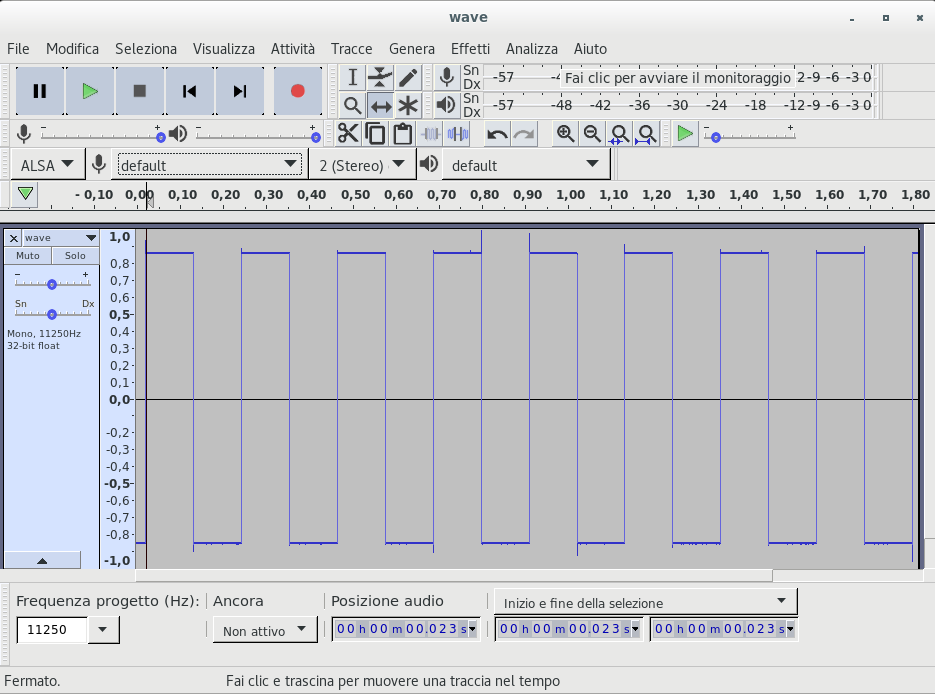
dumpscreen
Sometime is useful to dump the LCD screen of the oscilloscope
$ python test_visa.py dumpscreen --device USB0::62700::60986::SDS10PA1164640::0::INSTR --out screen.bmp
Conclusion
I think in the future I will return to this argument, in particular I want to try to continously read data from the oscilloscope but probably that is not possible for this kind of device, by the way there are a lot of commands that are missing that can be useful to interact with.
Modern cryptography: exercises chapter 2 'Perfectly secret encryption'
These are some solved exercises of chapter 2 of the book "Introduction to modern cryptography" by Jonathan Katz and Yehuda Lindell.
I'm not sure are correct but if anyone find any error let me know. It's a work in progress and more exercises will follow in future, when I finally find time to solve more. Also, enjoy my hand made diagrams :).
Implementing VGA interface with verilog
VGA stands for Video graphics array and it's one of the most
diffuse standard for video transmission; it roots its definition from
the way old catodic tubes work: the image is constructed one lines at times,
starting from the top and each line is displayed from the left to the right
(by the way this is the reason for the Y axes orientation in graphics
programming); physically this is done
by an electron beam guided from some electromagnets internal to the screen that hit the
pixels (?).
Following this scheme is easy enough imagine that the signals of this interface are the following
| Signal | Logic level | Description |
|---|---|---|
| VSYNC | 5V | Tells the monitor when a screen has been completed |
| HSYNC | 5V | Tells the monitor that a line has been completed |
| R | 0.7V | red color channel |
| G | 0.7V | green color channel |
| B | 0.7V | blue color channel |
To be a little more clear, below a time diagram stolen from this page
that implements a similar concept in VHDL.

The front porch and back porch are safety timing around the sync pulse (I think) to allow the old circuitery to have time to move the beam. During these periods the beam is not in condition to generate images.
These signals can vary a lot based on resolution/refresh time of the screen, but in my case I choosen to stick with the pretty standard 640x480@60Hz.
With this resolution I'll use the following value in pixel clock for the front, back porch and sync pulse
| front | sync | back | |
|---|---|---|---|
| HSYNC | 16pc | 96pc | 48pc |
| VSYNC | 10pc | 2pc | 33pc |
In my case I use a 25MHz clock as a pixel clock.
HDL
Now we can talk about its implementation with an hardware description language: I choose to use verilog because is the one that I know the most; in the following code, using the pixel clock, I increment the counters connected to the horizontal and vertical signals; when they reach their maximum values they are reset.
module hvsync_generator(
    input clk,
    output vga_h_sync,
    output vga_v_sync,
    output reg inDisplayArea,
    output reg [9:0] CounterX,
    output reg [9:0] CounterY
  );
    reg vga_HS, vga_VS;

    wire CounterXmaxed = (CounterX == 800); // 16 + 48 + 96 + 640
    wire CounterYmaxed = (CounterY == 525); // 10 + 2 + 33 + 480

    always @(posedge clk)
    if (CounterXmaxed)
      CounterX <= 0;
    else
      CounterX <= CounterX + 1;

    always @(posedge clk)
    begin
      if (CounterXmaxed)
      begin
        if(CounterYmaxed)
          CounterY <= 0;
        else
          CounterY <= CounterY + 1;
      end
    end

    always @(posedge clk)
    begin
      vga_HS <= (CounterX > (640 + 16) && (CounterX < (640 + 16 + 96)));   // active for 96 clocks
      vga_VS <= (CounterY > (480 + 10) && (CounterY < (480 + 10 + 2)));   // active for 2 clocks
    end

    always @(posedge clk)
    begin
        inDisplayArea <= (CounterX < 640) && (CounterY < 480);
    end

    assign vga_h_sync = ~vga_HS;
    assign vga_v_sync = ~vga_VS;

endmodule
when the signal inDisplayArea is logic true then the screen
is being drawn and the counters correspond to the pixel coordinate
on the screen.
No pixel data is created in this module, here
we are interested only to the sync signals generation. To generate a RGB
signal we need to couple this module with one that derive the pixel color
values from the counters: in the following module I use the last four
most significant bits of the x coordinate so to obtain a change of colour every 32 pixels:
module VGADemo(
    input clk_25,
    output reg [2:0] pixel,
    output hsync_out,
    output vsync_out
);
    wire inDisplayArea;
    wire [9:0] CounterX;

    hvsync_generator hvsync(
      .clk(clk_25),
      .vga_h_sync(hsync_out),
      .vga_v_sync(vsync_out),
      .CounterX(CounterX),
      //.CounterY(CounterY),
      .inDisplayArea(inDisplayArea)
    );

    always @(posedge clk_25)
    begin
      if (inDisplayArea)
        pixel <= CounterX[9:6];
      else // if it's not to display, go dark
        pixel <= 3'b000;
    end

endmodule
Hardware interface
From the hardware side of the interface you have to know that the monitor has an impedance of 75 Ohm for each color channel, so to obtain a 0.7V from a 3V3 logic level you have to use a serie resistor of 270 Ohm.
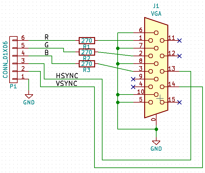
To note here that without using a DAC you can have only 8 colors as you can see in this image of my monitor

If you are interested in the complete project, exists a github repo with also other projects.
Create root filesystems for embedded systems
All is started from this link where a good boy shared some images in order to start to put hands on esotic architectures.
The bad thing in my opinion is that he doesn't explain how they have been generated,
just in case someone need to customize something; in this post I want to show how to create root filesystems for all
the necessary architectures using multistrap. If you want instead to use something more serious,
here another post about buildroot,
that allows you to do something similar.
Multistrap is a Debian tool used to create root filesystem: from the Debian's wiki
It was designed primarily for making root filesystems for foreign architecture embedded systems, but in fact can be used for many tasks where one might also use debootstrap.
Its main limitation compared to debootstrap is that it uses apt and dpkg directly so can only work on a debian system - debootstrap depends on nothing but shell, wget, binutils and thus can run pretty-much anywhere.
This is not a complete replacement for the images linked above since at the end
of the procedure won't have a linux kernel to use to start QEMU but I think
it's useful for someone with already a running instance.
Create the filesystem
The dependencies on a Debian system are
$ sudo apt-get install qemu multistrap qemu-user-static
since I am corageous I choose to create one root filesystem for the PowerPC architecture:
save the content below as multistrap.conf
[General]
directory=target-rootfs
cleanup=true
noauth=true
unpack=true
debootstrap=Grip Net Utils
aptsources=Grip
#tarballname=rootfs.tar
#
[Grip]
noauth=true
packages=apt kmod lsof
source=http://emdebian.bytesatwork.ch/mirror/grip
keyring=emdebian-archive-keyring
suite=stable-grip

[Net]
#Basic packages to enable the networking
packages=netbase net-tools udev iproute iputils-ping ifupdown isc-dhcp-client ssh

[Utils]
#General purpose utilities
packages=locales adduser nano less wget dialog usbutils
Then we can create a root fs using multistrap (the -a flag is what
sets the architecture)
$ sudo multistrap -a powerpc -f multistrap.conf -d /tmp/rootfs-ppc
$ sudo mount -o bind /dev/ /tmp/rootfs-ppc/dev
$ sudo cp /usr/bin/qemu-ppc-static /tmp/rootfs-ppc/usr/bin/
$ sudo LC_ALL=C LANGUAGE=C LANG=C chroot /tmp/rootfs-ppc/ dpkg --configure -a
select NO when asked to use dash as default shell. Now we can enter
inside the system and how can see now you have a PowerPC architecture
$ sudo chroot /tmp/rootfs-ppc/ /bin/bash
root@host:/# uname -a
Linux antani 4.9.0-3-amd64 #1 SMP Debian 4.9.30-2 (2017-06-12) ppc GNU/Linux
If you want an internet connection remember to mount --bind the
resolv.conf file inside the chroot.
If you want to create a real root filesystem for QEMU (or whatever) you can use the
following command after installing the libguestfs-tools package:
$ sudo virt-make-fs --format=qcow2 --size=+200M /tmp/rootfs-ppc/ /tmp/rootfs.img
(see virt-make-fs man page for more informations).
Probably in a following up post I will write about using projects like OpenEmbedded or buildroot to have a complete and customizable running systems.
The following signatures couldn't be verified error
Depending on the system you are in, multistrap can fail with this error,
from here
the advise is to add above the line in /usr/sbin/multistrap that contains
$config_str .= " -o Apt::Get::AllowUnauthenticated=true"
this line
$config_str .= " -o Acquire::AllowInsecureRepositories=true";