Implementing VGA interface with verilog
VGA stands for Video graphics array and it's one of the most
diffuse standard for video transmission; it roots its definition from
the way old catodic tubes work: the image is constructed one lines at times,
starting from the top and each line is displayed from the left to the right
(by the way this is the reason for the Y axes orientation in graphics
programming); physically this is done
by an electron beam guided from some electromagnets internal to the screen that hit the
pixels (?).
Following this scheme is easy enough imagine that the signals of this interface are the following
| Signal | Logic level | Description |
|---|---|---|
| VSYNC | 5V | Tells the monitor when a screen has been completed |
| HSYNC | 5V | Tells the monitor that a line has been completed |
| R | 0.7V | red color channel |
| G | 0.7V | green color channel |
| B | 0.7V | blue color channel |
To be a little more clear, below a time diagram stolen from this page
that implements a similar concept in VHDL.

The front porch and back porch are safety timing around the sync pulse (I think) to allow the old circuitery to have time to move the beam. During these periods the beam is not in condition to generate images.
These signals can vary a lot based on resolution/refresh time of the screen, but in my case I choosen to stick with the pretty standard 640x480@60Hz.
With this resolution I'll use the following value in pixel clock for the front, back porch and sync pulse
| front | sync | back | |
|---|---|---|---|
| HSYNC | 16pc | 96pc | 48pc |
| VSYNC | 10pc | 2pc | 33pc |
In my case I use a 25MHz clock as a pixel clock.
HDL
Now we can talk about its implementation with an hardware description language: I choose to use verilog because is the one that I know the most; in the following code, using the pixel clock, I increment the counters connected to the horizontal and vertical signals; when they reach their maximum values they are reset.
module hvsync_generator(
    input clk,
    output vga_h_sync,
    output vga_v_sync,
    output reg inDisplayArea,
    output reg [9:0] CounterX,
    output reg [9:0] CounterY
  );
    reg vga_HS, vga_VS;

    wire CounterXmaxed = (CounterX == 800); // 16 + 48 + 96 + 640
    wire CounterYmaxed = (CounterY == 525); // 10 + 2 + 33 + 480

    always @(posedge clk)
    if (CounterXmaxed)
      CounterX <= 0;
    else
      CounterX <= CounterX + 1;

    always @(posedge clk)
    begin
      if (CounterXmaxed)
      begin
        if(CounterYmaxed)
          CounterY <= 0;
        else
          CounterY <= CounterY + 1;
      end
    end

    always @(posedge clk)
    begin
      vga_HS <= (CounterX > (640 + 16) && (CounterX < (640 + 16 + 96)));   // active for 96 clocks
      vga_VS <= (CounterY > (480 + 10) && (CounterY < (480 + 10 + 2)));   // active for 2 clocks
    end

    always @(posedge clk)
    begin
        inDisplayArea <= (CounterX < 640) && (CounterY < 480);
    end

    assign vga_h_sync = ~vga_HS;
    assign vga_v_sync = ~vga_VS;

endmodule
when the signal inDisplayArea is logic true then the screen
is being drawn and the counters correspond to the pixel coordinate
on the screen.
No pixel data is created in this module, here
we are interested only to the sync signals generation. To generate a RGB
signal we need to couple this module with one that derive the pixel color
values from the counters: in the following module I use the last four
most significant bits of the x coordinate so to obtain a change of colour every 32 pixels:
module VGADemo(
    input clk_25,
    output reg [2:0] pixel,
    output hsync_out,
    output vsync_out
);
    wire inDisplayArea;
    wire [9:0] CounterX;

    hvsync_generator hvsync(
      .clk(clk_25),
      .vga_h_sync(hsync_out),
      .vga_v_sync(vsync_out),
      .CounterX(CounterX),
      //.CounterY(CounterY),
      .inDisplayArea(inDisplayArea)
    );

    always @(posedge clk_25)
    begin
      if (inDisplayArea)
        pixel <= CounterX[9:6];
      else // if it's not to display, go dark
        pixel <= 3'b000;
    end

endmodule
Hardware interface
From the hardware side of the interface you have to know that the monitor has an impedance of 75 Ohm for each color channel, so to obtain a 0.7V from a 3V3 logic level you have to use a serie resistor of 270 Ohm.
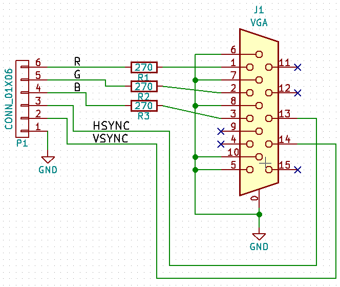
To note here that without using a DAC you can have only 8 colors as you can see in this image of my monitor

If you are interested in the complete project, exists a github repo with also other projects.
Comments
Comments powered by Disqus