Installing bootloader into ATMega328p
This is a standard thing to do with an ATMega328p, the core of
the Arduino development board: burn a bootloader into it and then
use a UART over USB connection to flash code into it.
There a lot of posts about this procedure, but are scattered all over the internet, without precise schematics and the low level stuffs.
In particular I want to install a bootloader into a pristine chip: its default configuration is different with respect to a standard Arduino setup, it works without external crystal and with a prescaler of 8 (i.e. the chip is running at 1MHz). These conditions are problematic if you want your bootloader to work with the correct baud rate.
What follow is intended as notes to use as quick reminder to myself with a little explanation of what's going on.
What's an ATMega?
First of all the ATMega328p is a microcontroller of the family ATMega (O 'RLY); there are a lot of chips in this family, with different features but take into account that it's not the only family (Wikipedia has a list of these families).
All of them are AVR chips, implementing an Harvard architecture
i.e. the memory addresses for RAM and executable code are separated: in
particular the flash (where the code you write will live after the uploading),
technically named program memory, it's divided in two sections
- Boot loader section located in the upper part of the program memory
- Application program section located at the start of the program memory
The important fact is that the start of the bootloader part is not fixed but can be configured.
The ATMega328p is pretty famous because is the microcontroller used with the Arduino: it has 28 pins, 23 of which are GPIO and 6 of which are for a 10 bit ADC.
For more informations read the datasheet.
I want to replicate with a breadbord the development workflow of an Arduino: flash a new program into the Application program section after connecting via a serial connection to the bootloader.
A thing to note here is that the bootloader is not always running (there is not an OS into the microcontroller, the system is real time), so in order to access the bootloader you have to reset the board and the bootloader must start after the reset.
Let see how to configurate the microcontroller and connect the components on the breadboard.
Fuses
Fuses are special one byte registers that contains persistent configuration values used to tell the microcontroller howto behave; in this case I need the following settings:
- the dimension for the boot section to be 256 words (in the
AVRworldwordsare 16 bit values); moreover the boot address will be0x3F00 - when reset the microcontroller must start at the boot address (technically speaking we need to configure the reset vector address)
There is a configuration regarding the clock that I don't need to change since is the value that is different from a standard Arduino setup: the table below show the default fuses for a pristine chip and for an Arduino Uno:
| Low | High | Extended | Clock frequency | |
|---|---|---|---|---|
| ATMega328 | 0x62 | 0xd9 | 0xff | 1MHz |
| Arduino Uno | 0xff | 0xde | 0x05 | 16MHz |
Each fuse comprehends a set of single bit values as showed
in the following table (more informations can be found in
the section Memory Programming of the datasheet)
| Extended | - | - | - | - | - | BODLEVEL2 | BODLEVEL1 | BODLEVEL0 |
| High | RSTDISBL | DWEN | SPIEN | WDTON | EESAVE | BOOTSZ1 | BOOTSZ0 | BOOTRST |
| Low | CKDIV8 | CKOUT | SUT1 | SUT0 | CKSEL3 | CKSEL2 | CKSEL1 | CKSEL0 |
The most significant bits are the left ones.
Note: fuses are weird, each bit is a boolean but programmed is assigned
to 0 and unprogrammed to 1 and moreover some bits of extended fuses are undefined
so some programmers fail to validate because returns the wrong (but equivalent) value:
for example for the extended fuse: 0xFD is equivalent to 0x05 (only bottom 3 bits are significant, and
Avrdude complains if the top bits are nonzero).
It's important to be sure what values you are modifing since in some cases it's possible to brick a microcontroller.
In my case I need only to change the bootloader section size and
the boot reset vector so a value of 0xDE for the high fuse will do
the job. And that is the only fuse that is necessary in order to
make the bootloader work.
Now I can set the high fuse with the following command:
$ avrdude -c buspirate -p atmega328p -P /dev/ttyUSB0 -U hfuse:w:0xDE:m
By the way for a more direct calculation of the fuses you can use this page.
Optiboot
This is a common bootloader that can be used with the Arduino IDE (the page for the standard Arduino bootloader is here).
Normally you can download a precompiled version but in my situation I need to recompile it to fit my setup. Before to compile we need to download the source code
$ git clone https://github.com/optiboot/optiboot && cd optiboot
and then enter into the directory containing the source code
$ cd optiboot/bootloaders/optiboot/
If your system is configured for autocompletion a make <TAB><TAB> should show you all the
available targets
atmega1280             atmega168p             atmega32_isp           attiny84               FORCE                  luminet                pro16_isp              virboot328             wildfirev3_isp
atmega1284             atmega168p_isp         atmega644p             baudcheck              isp                    luminet_isp            pro20                  virboot328_isp         xplained168pb
atmega1284_isp         atmega32               atmega8                bobuino                isp-stk500             mega1280               pro20_isp              virboot8               xplained328p
atmega1284p            atmega328              atmega88               bobuino_isp            lilypad                mega1280_isp           pro8                   wildfire               xplained328pb
atmega16               atmega328_isp          atmega88_isp           clean                  lilypad_isp            mighty1284             pro8_isp               wildfirev2
atmega168              atmega328_pro8         atmega88p_isp          diecimila              lilypad_resonator      mighty1284_isp         sanguino               wildfirev2_isp
atmega168_isp          atmega328_pro8_isp     atmega8_isp            diecimila_isp          lilypad_resonator_isp  pro16                  sanguino_isp           wildfirev3
Before to finally compile it I have to indicate that my setup doesn't include an external
crystal, i.e. the clock frequency is 1MHz; bad enough this cause a problem with the default UART baud rate: given a frequency not all
the baud rates are possible because of sampling errors, so if we launch the compilation
with the custom frequency but without changing the default baud rate (115200) the process fails
$ make atmega328 AVR_FREQ=1000000L
avr-gcc (GCC) 4.9.2
Copyright (C) 2014 Free Software Foundation, Inc.
This is free software; see the source for copying conditions.  There is NO
warranty; not even for MERCHANTABILITY or FITNESS FOR A PARTICULAR PURPOSE.

BAUD RATE CHECK: Desired: 115200, Real: 125000, UBRRL = 0, Error=8.5%
avr-gcc -g -Wall -Os -fno-split-wide-types -mrelax -mmcu=atmega328p -DF_CPU=1000000L  -DBAUD_RATE=115200 -DLED_START_FLASHES=3        -c -o optiboot.o optiboot.c
optiboot.c:303:6: error: #error BAUD_RATE error greater than 5%
     #error BAUD_RATE error greater than 5%
      ^
optiboot.c:314:2: error: #error Unachievable baud rate (too fast) BAUD_RATE
 #error Unachievable baud rate (too fast) BAUD_RATE
  ^
<incorporato>: set di istruzioni per l'obiettivo "optiboot.o" non riuscito
make: *** [optiboot.o] Errore 1
The AVR_FREQ value is super important: it tells what frequency the microcontroller
runs at, if this is wrong all the timing-related functionalities are not gonna to work.
Luckily we can configure the correct value for the baud rate using BAUD_RATE (in this case I use the minimal value that
I can come up with)
$ make atmega328 BAUD_RATE=9600 AVR_FREQ=1000000L
Note: I should have used the atmega328_isp target but the weird behaviour for the
extended fuses causes the ISP to fail when it tries to validate the changed fuse since
some bits are undefined and if the programmer writes this as 1 is possible that reads back
zero when verifies it, making the process fail.
By the way, if you want to use the bus pirate as ISP programmer
it's possible to call directly the _isp target like indicated below
$ make atmega328_isp BAUD_RATE=9600 AVR_FREQ=1000000L ISPTOOL=buspirate ISPPORT=/dev/ttyUSB0 ISPSPEED=-b115200
By the way, I flashed it with avrdude directly in a separate step
$ avrdude -c buspirate -p m328p -P /dev/ttyUSB0 -U flash:w:optiboot_atmega328.hex
Breadboard
The schematics used to place the components on the breadboard is the following
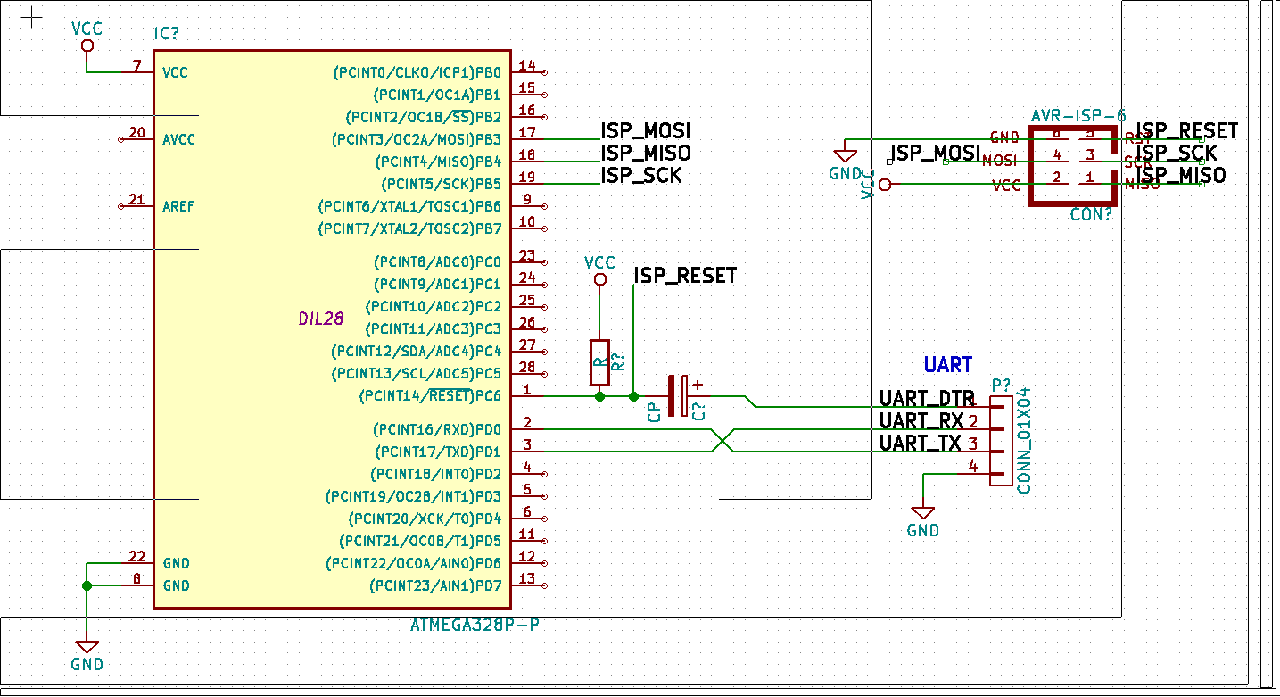
Two connectors are initialy needed: the ISP to flash
the bootloader and the UART to communicate with the bootloader.
The first can be removed once the bootloader is in place and works ok.
Personally I created a breakout that exposes the 6 ISP related pins
and then flash using some pogo pins.
The thing important to note is the connection between DTR and RESET that
allows the board to be reset when uploading the code and
in particular the capacitor between them:
without it the chip won't reset and won't enter the bootloader. I don't
understand why: someone says that "the level on this signal line changes when
the serial bridge is connected (enabled in software).
However on the reset you only want a pulse. The capacitor acts as
a differentiator".
Also important are the values: experimentally I found that a resistor of 10K and a capacitor of 0.1uF work well.
Also remember to place a big capacitor between power rails in order to make the system more stable: if you are experiencing random resets or odd behaviours probably the chip suffers from an unstable power line.
Programming
Now it's time to try to flash some application using the bootloader:
Optiboot declares that uses the stk500v1 protocol
corresponding to the arduino programmer type (flag -c of avrdude).
First of all I'll try to comunicate with the board
$ avrdude -c arduino -p m328p -P /dev/ttyUSB0 -b 9600
If all is ok we can try to write a minimal snippet of code that toggle the logic level
of pin PB5 (save it in a file named main.c)
#include <avr/io.h>
#include <util/delay.h>

#define BLINK_DELAY_MS 1000

int main() {
 /* set pin 5 of PORTB for output*/
 DDRB |= _BV(DDB5);

 while(1) {
  /* set pin 5 high to turn led on */
  PORTB |= _BV(PORTB5);
  _delay_ms(BLINK_DELAY_MS);

  /* set pin 5 low to turn led off */
  PORTB &= ~_BV(PORTB5);
  _delay_ms(BLINK_DELAY_MS);
 }
}
This is also very good to check that the clock is set correctly and we haven't screw up the fuses.
We can use the Arduino build system to save time : create a file named
Makefile and place in the same directory as main.c with the
following content:
BOARD_TAG    = uno
F_CPU        = 1000000L
MONITOR_PORT = /dev/ttyUSB0

AVRDUDE_ARD_BAUDRATE   = 9600

include /usr/share/arduino/Arduino.mk
Now it's possible to compile and upload with the simple command
$ make -C source_dir/ upload
NB: the Arduino build system is installable in a Debian-like system
with the package arduino-mk.
Comments
Comments powered by Disqus