VGA controller simulation with verilator
In my two previous posts I implemented a simple VGA controller and one with the text mode but now I want to explore
the possibility to simulate it using verilator.
I'll simply describe how to generate C++ code from the design and use some
native code to obtain a graphical output from it. I'm not an expert
and these are a couple of experiments I did, if you want something more interesting
go for example to zipcpu's site.
Verilator
In practice verilator generates C++ code that simulates your design:
suppose you have a verilog module, you can use the following commands
$ verilator -I<path/containing/verilog> -Wall -cc <verilog main module> --exe <c++ simulation files>
$ make -C obj_dir -j 8 -f V<module name> V<module name>
these generate a obj_dir directory with some C++ code
and a Makefile that can generate an executable using the simulation
files passed as initial arguments to verilator.
verilator use the module's name from the verilog file and create a C++
class whose name is the module's name prefixed with with an uppercase v, so
if your module is named foo the corresponding C++ class is named
Vfoo. You don't have to indicate all the verilog files, but only the "top"
one, verilator will use the paths passed using -I to find the "dependencies"
for it.
Here an example: to improve from the previous post about the Text mode where I used
a block memory with Xilinx's primitive, now I'm going to implement the ROM for
the glyphs using standard verilog; it's not difficult and makes the controller
not depending from the pretty bad Xilinx's proprietary tools.
As you can see it's pretty simple, it's like a "huge flip-flop"
`timescale 1ns / 1ps
`default_nettype none

module glyph_rom(
    input wire clk,
    input [13:0] addr,
    output reg [0:0] data
);

reg [0:0] rom[16383:0];

initial begin
    $readmemh("path/to/glyph.mem", rom);
end

always @(posedge clk) begin
    data <= rom[addr];
end

endmodule
the interesting part is the $readmemh() function that reads a file containing
the right number of entries for the data type we are trying to fill (in this case
16384 1-bit values) written as single hexadecimal value (in ASCII). The $readmemh()
function should be synthetizable but I haven't such experience with the FPGA toolchains
to know for sure :)
It's all fine and good, but now I want to simulate it, I want to be sure that it outputs the right glyph at the right address so I wrote the following simulation
#include <stdlib.h>
#include "Vglyph_rom.h"
#include "verilated.h"

#define LOG(...) fprintf(stderr, __VA_ARGS__)


int main(int argc, char *argv[]) {
    LOG(" [+] starting Glyph ROM simulation\n");
    uint64_t tickcount = 0;

    Vglyph_rom* g_rom = new Vglyph_rom; // [1]

    printf("[character code %x]\n", tickcount >> 7);
    for ( ; tickcount < 16834 ; ) {
        g_rom->addr = tickcount; // [2]
        g_rom->clk = 0;
        g_rom->eval();           // [3a]

        g_rom->clk = 1;
        g_rom->eval();           // [3b]

        if (((tickcount % 8) == 0) && tickcount) {
            printf("\n");
        }

        if ((tickcount % (8 * 16)) == 0 && tickcount) {
            printf("[character code %x]\n", tickcount >> 7);
        }
        printf("%c", g_rom->data ? '#' : ' '); // [4]


        g_rom->clk = 0;
        g_rom->eval();

        tickcount++;
    }

    return EXIT_SUCCESS;
}
At [1] we created the C++ class instance that handle our module,
and we are using the variable tickcount to explore all the addresses in order
([2]); to simulate a clock cycle we set the logic level of the clock first as
low and then high using eval() to tell the instance to internally simulate the
behaviour of the module ([3a] and [3b]). Finally we print the value returned
by the ROM using the character # to indicate a 1 value and the space
character otherwise (it's more readable than 0 and 1).
Now it's time to try it out
$ verilator -Isim/../source/  -Wall -cc ../source/glyph_rom.v --exe glyph_rom.cpp
$ make -C obj_dir -j 8 -f Vglyph_rom.mk Vglyph_rom
$ ./obj_dir/Vglyph_rom
 ...
[character code 25]


##    #
##   ##
    ##
   ##
  ##
 ##
##   ##
#    ##


[character code 26]


  ###
 ## ##
 ## ##
  ###
 ### ##
## ###
##  ##
##  ##
##  ##
 ### ##
...
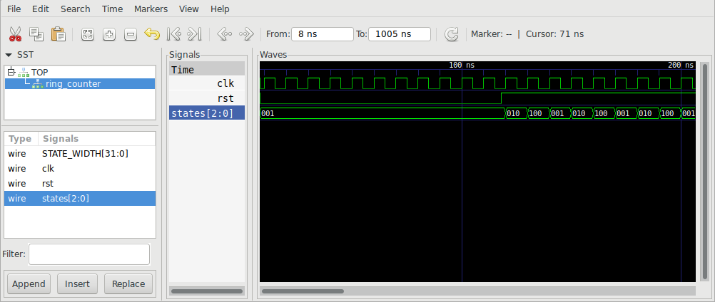
In this case is pretty simple but, in certain cases you want to have a trace of the different signals, take for example a ring counter.
A ring counter is a type of counter composed of flip-flops connected into a shift register, with the output of the last flip-flop fed to the input of the first, making a "circular" or "ring" structure; a simple implementation is the following
`default_nettype none

module ring_counter#(parameter STATE_WIDTH=3)(
    input clk,
    input rst,
    output reg [STATE_WIDTH - 1:0] states
);

/*
 * Be sure that the module starts in a consistent state
 */
initial begin;
    states = 3'b1;
end

always @(posedge clk) begin
    if (~rst)
        states <= 3'b1;
    else begin
        states <= states << 1;
        states[0] <= states[STATE_WIDTH - 1];
    end
end

endmodule
and here is the simulation
#include <stdlib.h>
#include "Vring_counter.h"
#include "verilated_vcd_c.h"
#include "verilated.h"


void tick(uint64_t tickcount, Vring_counter* v, VerilatedVcdC* tfp) {
    v->eval();
    if (tfp)
        tfp->dump(tickcount*10 - 2);
    v->clk = 1;
    v->eval();
    if (tfp)
        tfp->dump(tickcount*10);
    v->clk = 0;
    v->eval();
    if (tfp) {
        tfp->dump(tickcount*10 + 5);
        tfp->flush();
    }
}

int main(int argc, char **argv) {
    uint64_t tickcount = 0;
    // Initialize Verilators variables
    Verilated::commandArgs(argc, argv);

    Verilated::traceEverOn(true);
    VerilatedVcdC* tfp = new VerilatedVcdC;

    // Create an instance of our module under test
    Vring_counter *tb = new Vring_counter;
    tb->rst = 0;

    tb->trace(tfp, 99);
    tfp->open("ring_counter_trace.vcd");

    // Tick the clock until we are done
    for (unsigned int count = 0; count < 100 ; count++) {
        if (tickcount > 10) {
            tb->rst = 1;
        }
        tick(++tickcount, tb, tfp);
    }

    exit(EXIT_SUCCESS);
}
You must add the --trace flag to verilator and include verilated_vcd_c.h
in your C++ code in order to be able to generate traces.
The program when launched generates ring_counter_trace.vcd that can be
opened into gtkwave in order to see the signals and their temporal evolution
eval
From the documentation about eval
When eval() is called Verilator looks for changes in clock signals and evaluates
related sequential always blocks, such as computing always_ff @ (posedge...)
outputs. Then Verilator evaluates combinatorial logic.

Note combinatorial logic is not computed before sequential always blocks are
computed (for speed reasons). Therefore it is best to set any non-clock inputs
up with a separate eval() call before changing clocks.

Alternatively, if all always_ff statements use only the posedge of clocks, or
all inputs go directly to always_ff statements, as is typical, then you can
change non-clock inputs on the negative edge of the input clock, which will be
faster as there will be fewer eval() calls.
Compiler flags
It's possible to indicate particular flags to the compiler using -CFLAGS
with verilator, like enabling warnings, otherwise you could compile you code without seeing any
warning and thinking there are no issue; remember that you can debug with gdb
your design if you pass -g to the compiler.
Defines
Also verilog can use preprocessing variables and verilator adds a few of
them during the compilation, you can use the following one-liner to obtain the
predefined ones
$ touch foo.v ; verilator -E --dump-defines foo.v
`define SV_COV_ASSERTION 20
`define SV_COV_CHECK 3
`define SV_COV_ERROR -1
`define SV_COV_FSM_STATE 21
`define SV_COV_HIER 11
`define SV_COV_MODULE 10
`define SV_COV_NOCOV 0
`define SV_COV_OK 1
`define SV_COV_OVERFLOW -2
`define SV_COV_PARTIAL 2
`define SV_COV_RESET 2
`define SV_COV_START 0
`define SV_COV_STATEMENT 22
`define SV_COV_STOP 1
`define SV_COV_TOGGLE 23
`define SYSTEMVERILOG 1
`define VERILATOR 1
`define coverage_block_off /*verilator coverage_block_off*/
`define systemc_clock /*verilator systemc_clock*/
`define verilator 1
`define verilator3 1
so, if for example, you want to define a custom UART baud generator when
simulating your design, you can put custom code when VERILATOR is defined.
VGA simulation
Now that we have introduced verilator we can think about simulating the
complete VGA controller; the verilog code is not included in the post because is
the same as in the previous post, only with the glyph ROM and text RAM
reimplemented.
The simulation is the following:
#include <fcntl.h>
#include <stdlib.h>
#include "VVGA.h"
#include "verilated.h"

#define LOG(...) fprintf(stderr, __VA_ARGS__)

bool needDump = false; /* when the vsync signal transition from low to high */
bool old_vsync = true;

int main(int argc, char *argv[]) {
    LOG(" [+] starting VGA simulation\n");
    uint64_t tickcount = 0;

    VVGA* vga = new VVGA; // [1]

    vga->rst = 0;         // [2]

    /* bad enough 24bits data type doesn't exist! */
    uint8_t image[801*526*3]; /* FIXME: should be 800*525 */ // [3]
    memset(image, 'A', sizeof(image));

    uint32_t idx = 0;

    unsigned int count_image = 0;

    for ( ; count_image < 10; ) {
        if (tickcount > 10) {
            vga->rst = 1;           // [4]
        }
        vga->clk = 0;
        vga->eval();

        vga->clk = 1;
        vga->eval();                 // [5]

        /* we need to dump when vsync transitions from low to high */
        needDump = (!old_vsync && vga->vsync_out);  // [6]

        if (needDump) {
            char filename[64];
            snprintf(filename, 63, "frames/frame-%08d.bmp", count_image++);
            LOG(" [-> dumping frame %s at idx %d]\n", filename, idx);
            int fd = creat(filename, S_IRUSR | S_IWUSR);

            if (fd < 0) {
                perror("opening file for frame");
                break;
            }

            char header[] = "P6\n801 526\n255\n"; // [7]

            write(fd, header, sizeof(header));
            write(fd, image, sizeof(image));

            close(fd);

            idx = 0;
        }

        image[idx++] = ((vga->pixel & 1) * 0xff);        // [8]
        image[idx++] = ((vga->pixel & 2) >> 1) * 0xff;
        image[idx++] = ((vga->pixel & 4) >> 2) * 0xff;

        old_vsync = vga->vsync_out;

        tickcount++;
    }

    return EXIT_SUCCESS;
}
As previously, we instantiate the module ([1]) and set the rst signal low so to
reset the module ([2]); to store the frames we allocate in memory
enough to store 801x526 pixels with 3 colors ([3]).
After ten clock cycles we exit from the reset state ([4]), meanwhile
we simulate the module ([5]) and save the pixel in memory ([8])
and check if it's time to dump a frame ([6]).
The mechanism it's very simple: waits for the "positive" vsync transition in order
to dump a bmp ([7]) with all the pixels transmitted by the controller; take
in mind that is dumping also the part non directly displayed by a normal
monitor, including back porch, front porch and sync pulse, so the original
resolution 640x480 becames 800x550.
It dumps a couple of frames and then exits; here an example:
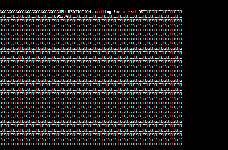
So in theory you could develop your design without going back and forth with your FPGA, but take in mind that I'm a n00b in this field so maybe I'm missing something :) As always the code is available on github.
My next step is to implement an instruction set and build a processor in order to do something with our screen, stay tuned.
Comments
Comments powered by Disqus