From zero to hero
A couple of years ago a friend of mine asked me to take a look at a pico projector that he had bricked during an update. He hadn't tried anything fancy or dangerous, he had simply used the internal functionality of the device. At that point in time the device was stuck in a bootloop with the Samsung logo as the only output from the projector.
I obviously accepted to take a look and in this way started a journey that lasted like five years where I learned a lot about hardware and software.
Information gathering
The device in question is the Samsung Pico Projector SP-H03, this is the product page; this item has been discontinued and from the few reviews I have seen it didn't do very well commercially.
The user manual doesn't talk about upgrading and it seems there isn't any post in the internet talking about some particular flashing mode for this device; I'm on my own to discover.
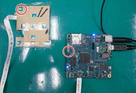
Opening the device is possible to unveil the internals: on top there is a PCB
with SMD components on both the sides
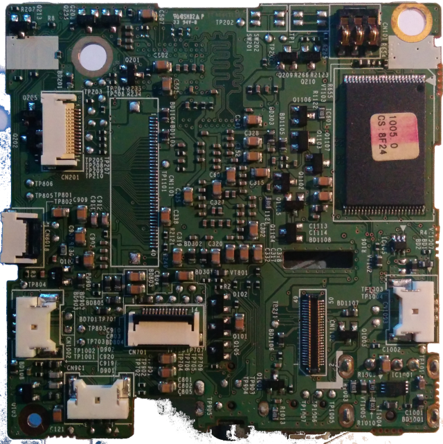
but no signs of a connector for the UART: indeed my idea throughout
the investigation will be to discover the serial port and find out
why the system doesn't work.
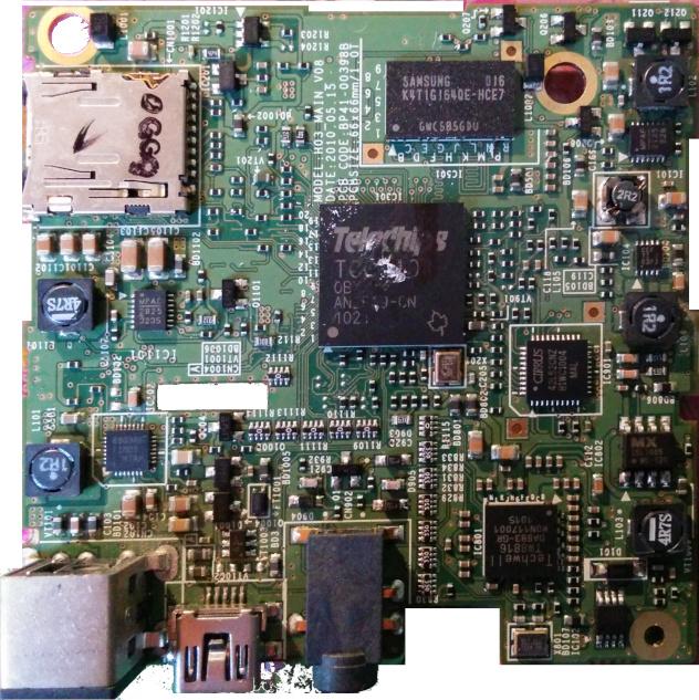
From the front image I found that the main chip for this box is the TCC9101,
a pratically unknown SoC used in a couple of other devices and cited in the
Wikipedia page about ARM SoCs
as an ARM1176JZ(F)-S, i.e. an ARMv6 architecture. Take in mind that not even
the company producing the chip, Telechips, has a page specific about this chip, only
cited in a page.
Firmware
Another thing available to look at is the firmware update that you can download
from the official site: P-OBRNPWWC-1008.1.rom.
With my incredible skills I discovered that is a simple tar archive
$ file Pico\ SP-H03/P-OBRNPWWC-1008.1.rom
Pico SP-H03/P-OBRNPWWC-1008.1.rom: POSIX tar archive (GNU)
containing some files
$ tar -tf Pico\ SP-H03/P-OBRNPWWC-1008.1.rom
./
./wplayer
./opt/
./opt/qt/
./opt/qt/lib/
./opt/qt/lib/libQtNetwork.so.4
./opt/qt/lib/libQtGui.so.4
./opt/qt/lib/fonts/
./opt/qt/lib/fonts/unifont_160_50.qpf
./opt/qt/lib/fonts/Oberon_chn_kor_20091217.ttf
./opt/qt/lib/fonts/langpack_cjk.dat
./opt/qt/lib/libQtCore.so.4
./pico_player
./ui/
  more stuffs
./TCCKernel7.3.rom
./setup/
./setup/reg_set.obn
./md5sum
./TCCBoot4.2.rom
./run.sh
./pico
The most promising for further investigation are TCCKernel7.3.rom and TCCBoot4.2.rom
$binwalk Pico\ SP-H03/P-OBRNPWWC-1008.1/TCCBoot4.2.rom

DECIMAL       HEXADECIMAL     DESCRIPTION
--------------------------------------------------------------------------------

$ binwalk Pico\ SP-H03/P-OBRNPWWC-1008.1/TCCKernel7.3.rom

DECIMAL       HEXADECIMAL     DESCRIPTION
--------------------------------------------------------------------------------
55177         0xD789          Certificate in DER format (x509 v3), header length: 4, sequence length: 1416
59013         0xE685          Certificate in DER format (x509 v3), header length: 4, sequence length: 13588
78208         0x13180         gzip compressed data, maximum compression, from Unix, last modified: 2010-07-27 01:42:34
4720605       0x4807DD        Certificate in DER format (x509 v3), header length: 4, sequence length: 5376
5024709       0x4CABC5        Certificate in DER format (x509 v3), header length: 4, sequence length: 1328
5419085       0x52B04D        Certificate in DER format (x509 v3), header length: 4, sequence length: 4866
5531093       0x5465D5        Certificate in DER format (x509 v3), header length: 4, sequence length: 1292
5702529       0x570381        Certificate in DER format (x509 v3), header length: 4, sequence length: 13588
6446763       0x625EAB        Linux kernel version 2.6.28
6477872       0x62D830        CRC32 polynomial table, little endian
6821729       0x681761        Unix path: /dev/vc/0
6834593       0x6849A1        IMG0 (VxWorks) header, size: 1111564346
looking at the strings inside you can have some clues
$ strings Pico\ SP-H03/P-OBRNPWWC-1008.1/TCCBoot4.2.rom | grep -i tele
TELECHIPS01
TELECHIPS02
TELECHIPS03
TELECHIPS04
$ strings Pico\ SP-H03/P-OBRNPWWC-1008.1/TCCBoot4.2.rom | grep -i boot
    tcboot ver %s for %s Linux
tcboot.rom
Updating tcboot.rom ->
$ strings Pico\ SP-H03/P-OBRNPWWC-1008.1/TCCKernel7.3.rom | grep -i samsung
Samsung Oberon Board
Samsung Info. Systems America, Inc.
Samsung
SAMSUNG
$ strings Pico\ SP-H03/P-OBRNPWWC-1008.1/TCCBoot4.2.rom | grep -i usb
SIGBYAHONG_USB_MANAGER_LINUX_TCC89XX_V2.000
SIGBYAHONG_USBPHY_LINUX_TCC89XX_V2.000
SIGBYAHONG_USB_DEVICE_LINUX_TCC89XX_V2.000
MAX8903A: USB Input.
So we can deduce that the board has as codename Oberon and that is based
on the TCC89XX SoC.
This SoC has a little more information (by the way, a similar named SoC, the TCC8920, is
a complete different ARM revision so I don't know what to think anymore about
the naming convention used by Telechips) and indeed is possible to find
a torrent containing a lot of leaked materials about this family of chips
(f21b0242eac7f91090eaa949c699d2bc9252ca85 is the hash of such torrent);
the datasheet is comprised in the leak.
Reversing
With the datasheet in my hands I started to reversing the supposed bootloader
contained in the firmware update, at first using radare2 but when ghidra
has been officialy released I switched to it making easier the process.
The reversing was not strictly necessary for the process I'm describing
but helped me to exercise with the assembly and to know better the peripherals
available on the device. In particular after have done it I was sure that
TCCBoot4.2.rom was really the bootloader.
The first problem to overcome was to understand the header and the address where the bootloader is loaded: the first thing was pretty simple since I discovered a repository containing the source code of such bootloader (it would not have been such hard to deduce the fields looking at them or via the code in the bootloader).
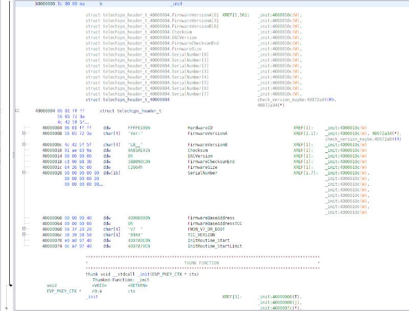
Looking at a few addresses called from the firmware was apparent that
it loads at 0x40000000.
Knowing that, and the address mapping from the datasheet, I set the following in ghidra
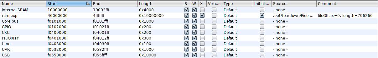
that are not perfect but good enough to allow a decent reversing; part of the mapping reported in the datasheet is the following
| Address space | Device name |
|---|---|
0x00000000 - 0x0fffffff
|
remapped region |
0x10000000 - 0x10003fff
|
16kB on-chip RAM |
0x40000000 - 0x4fffffff
|
off-chip SDRAM |
0xf0000000 - 0xffffffff
|
on-chip peripherals |
moreover the peripherals memory space is partitioned like the following
| Base address | Peripherals |
|---|---|
0xf0000000 |
Graphic bus |
0xf0100000 |
Memory bus |
0xf0200000 |
DDI bus |
0xf0300000 |
Memory bus |
0xf0400000 |
System control |
0xf0500000 |
IO bus |
0xf0600000 |
MMU table |
0xf0700000 |
Video bus |
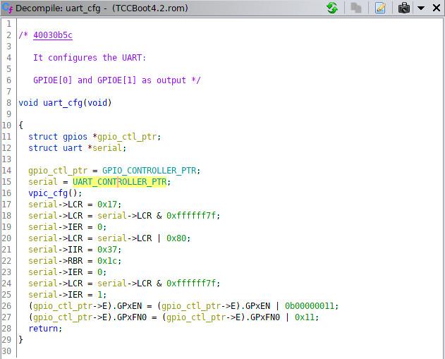
It's amazing how with ghidra is possible to describe the registers that control for example
the UART subsystem with a struct
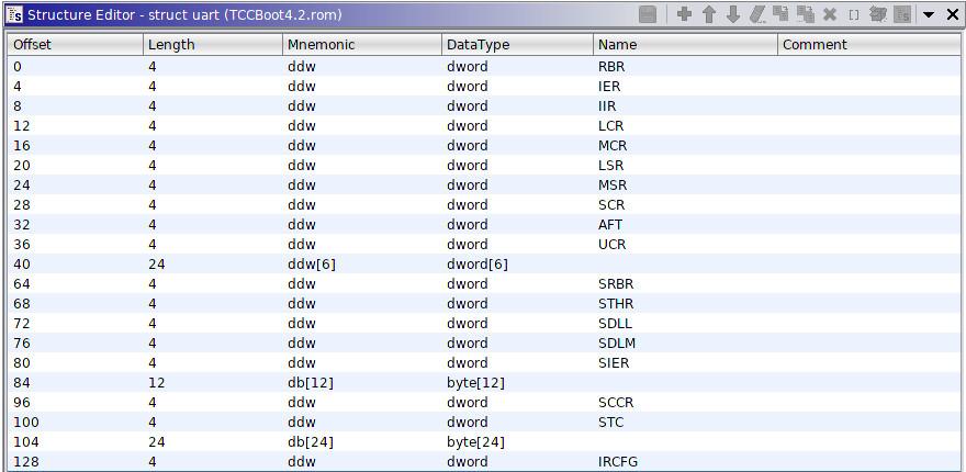
and obtain a perfectly readable decompiled code
FWDN
From the reading of several documents the presence of a USB update process
seems pretty solid: in the datasheet itself is cited a so called USB boot mode
that works in the following way
- The TCC8900 makes internal SRAM area starts from zero, and copies USB interrupt service routine to internal SRAM area.
- It waits until USB connection is established.
- Once it is connected, host transfers first the parameter for USB loader routine including start address, destination address and the amount of data to be transferred (with a unit of packet).
- The TCC8900 starts communicating between a host PC with fixed amount of data which is called as packet. The packet size of TCC8900 is 512 bytes.
- At every successful reception of packet, it copies them where the destination address pointed, and after all amount of data has been copied, it starts program where the start address pointed
It's similar of what is described in the datasheet of
TCC760
or that other people
have found;
it loads via the tcctool
some code in SDRAM and executes it.
I discovered via the service manual (in chinese) that to enter in this mode you have to press a button (that is not soldered in my case) when you start the device (since the device has a touch surface with the power button on a side is a little tricky to press both at the same time)
Another approach is to short the CE pin of the NAND. What you see is a new USB device
turing kernel: usb 2-2: new high-speed USB device number 3 using xhci_hcd
turing kernel: usb 2-2: config 1 interface 0 altsetting 0 bulk endpoint 0x82 has invalid maxpacket 64
turing kernel: usb 2-2: config 1 interface 0 altsetting 0 bulk endpoint 0x1 has invalid maxpacket 64
turing kernel: usb 2-2: New USB device found, idVendor=140e, idProduct=b077
turing kernel: usb 2-2: New USB device strings: Mfr=0, Product=0, SerialNumber=0
turing kernel: usb 2-2: USB disconnect, device number 3
Modifing the code of tcctool, adding the correct VID:PID values and other minor
modifications, I was able to execute code in the board and I started to write a piece
of assembler code to toggle all the GPIO pins in order to find out where the serial
was located on the board. There are 6 banks of GPIO with up to 32 pins each
and to discover which GPIO corresponds to a given pin I driven it with a PWM signal
having \(\hbox{bank} << 5\, |\, \hbox{id} \) cycles.
This below is the code
; https://stackoverflow.com/questions/6139952/what-is-the-booting-process-for-arm
    .text
    .align  2
    .syntax unified
    .arm
    .fpu softvfp
    .type   __entry, %function
    .type   enable_watchdog, %function
    .type   gpio_identification, %function
    .type   gpio_signal, %function
    .type   watchdog_clear, %function
    .type   _delay, %function
/*
 * Since we have not stack available for now (no hard constraint, we are only lazy)
 * we call routines and use r10, r11 and r12 as temporary registers to save lr.
 *
 * KEEP IN MIND THE LEVEL OF NESTING A FUNCTION IS CALLED!
 */
__entry:
    bl enable_watchdog
gpio:
    bl gpio_identification @ uses r10
    bl watchdog_clear
    b gpio

.set  EN, (1<<0)
.set IEN, (1<<3)
.set TCKSEL, (1<<4)
.set WATCHDOG_EN, (1<<31)
.set WATCHDOG_CLR, (1<<30)

enable_watchdog:
    mov r10, lr
    ldr r3, .TWDCFG
    ldrb    r4, [r3]
    orr r4, r4, #(EN | IEN)
    strb    r4, [r3]
    ldrb    r4, [r3]
    bic r4, r4, 0x30 @ clear the TCKSEL
    orr r4, r4, 0x40 @ set the TCKSEL to 0x04
    strb    r4, [r3]
    ldr r3, .TWDCLR_ADDR
    mov r4, #0x00000000
    str r4, [r3]
    ldr r3, .WATCHDOG_ADDR
    ldr r4, [r3]
    orr r4, r4, #WATCHDOG_EN
    str r4, [r3]
    mov lr, r10
    mov pc, lr

watchdog_clear:
    mov r12, lr
    ldr r0, .WATCHDOG_ADDR
    ldr r1, [r0]
    orr r1, r1, #WATCHDOG_CLR
    str r1, [r0]
    mov lr, r12
    mov pc, lr

.CONTROL_ADDR:
    .word   0xf0404000
.TWDCFG:
    .word   0xf0403070
.TWDCLR_ADDR:
    .word   0xf0403074
.WATCHDOG_ADDR:
    .word   0xf040400c

.set CONTROL_POFF, (1<<1)

power_off:
    ldr r3, .CONTROL_ADDR
    ldr r4, [r3]
    orr r4, r4, #CONTROL_POFF
    str r4, [r3]
/*
 * This function outputs via the GPIO, passed as the couple (group, idx)
 * its encoded identifier as a 32 bit number.
 *
 *  r8: group in [0, 5]
 *  r9: idx in [0, 31]
 *
 * so we need a number of bits to encode 6*32 = 192 values, i.e. 8bit are enough,
 * but we can use all 32-bit so that we have a start/stop pattern clearly
 * identifiable.
 *
 */
.set GPIO_GROUP_OFFSET,  0x40
.set GPIO_GPxDAT_OFFSET, 0x00
.set GPIO_GPxEN_OFFSET,  0x04
.set GPIO_GPxCLR_OFFSET, 0x0c
.set GPIO_GPxXOR_OFFSET, 0x10
.set GPIO_GPxPD0_OFFSET, 0x1c
.set GPIO_GPxPD1_OFFSET, 0x20
.set GPIO_GPxFN0_OFFSET, 0x24
.set GPIO_GPxFN1_OFFSET, 0x28
.set GPIO_GPxFN2_OFFSET, 0x2c
.set GPIO_GPxFN3_OFFSET, 0x30
gpio_signal:
    mov r11, lr                     @ save the return pointer
    /* initialize the GPIO requested in OUTPUT mode */
    ldr r3, .GPIO_REGISTER_MAP_ADDR
    mov r7, #GPIO_GROUP_OFFSET
    mul r4, r8, r7
    add r5, r3, r4                 @ r5 points at the start of the right GPIO group address
    add r6, r5, #GPIO_GPxEN_OFFSET @ r6 points to the direction control
    mov r7, #1
    lsl r7, r9                     @ r7 contains the pattern for the right GPIO to be activated
    str r7, [r6]                   @ set OUTPUT MODE
    /* set pull-down */
    add r6, r5, #GPIO_GPxPD0_OFFSET
    ldr r3, .GPIO_PULL_DOWN
    str r3, [r6]
    add r6, r5, #GPIO_GPxPD1_OFFSET
    ldr r3, .GPIO_PULL_DOWN
    str r3, [r6]
    /* and set function mode to 0 */
    add r6, r5, #GPIO_GPxFN0_OFFSET
    mov r3, #0
    str r3, [r6]
    add r6, r5, #GPIO_GPxFN1_OFFSET
    mov r3, #0
    str r3, [r6]
    add r6, r5, #GPIO_GPxFN2_OFFSET
    mov r3, #0
    str r3, [r6]
    add r6, r5, #GPIO_GPxFN3_OFFSET
    mov r3, #0
    str r3, [r6]

    /* from now on, we need to loop over the encoding */
    orr r4, r9, r8, LSL #5         @ r4 contains the number of cycles to toggle the GPIO
    mov r3, #0                     @ this will be our counter
    add r6, r5, #GPIO_GPxXOR_OFFSET @ r6 points at the GPxXOR register
_loop_over_encoding:
    str r7, [r6]                   @ we toggle the corresponding register
    ldr r0, .DELAY_VALUE
    bl _delay
    str r7, [r6]                   @ twice so to have a square wave
    bl _delay
    cmp r3, r4
    add r3, r3, #1
    bne _loop_over_encoding

    /* now set to zero the GPIO */
    add r6, r5, #GPIO_GPxCLR_OFFSET
    str r7, [r6]

    /* return at home */
    mov lr, r11
    mov pc, lr
.DELAY_VALUE:
    .word   0xf
.GPIO_REGISTER_MAP_ADDR:
    .word   0xf0102000
.GPIO_PULL_DOWN:
    .word   0xaaaaaaaa
.set GPIO_GROUPS_N, 0x06
.set GPIO_IDX_N,    0x20

gpio_identification:
    mov r10, lr

    mov r8, #0
_loop_group:
    mov r9, #0
_loop_idx:
    bl  gpio_signal
    add r9, r9, #1
    cmp r9, #GPIO_IDX_N
    bne _loop_idx
    add r8, r8, #1
    cmp r8, #GPIO_GROUPS_N
    bne _loop_group

    mov lr, r10
    mov pc, lr

/* takes r0 as number of loop to wait
 * internally uses r1 and r2
 */
_delay:
    mov r2, lr
    mov r1, #0x00
_loop_delay:
    cmp r1, r0
    add r1, r1, #1
    bne _loop_delay
    mov lr, r2
    mov pc, lr
I also wrote a program to help me debug the code I was using (I would call it
emulator but it simply allocates the memory where to execute the firmware at
the same address of the real device and then jumps into it, this is inspired from the work of
Travis Goodspeed with the MD380).
Obviously you need qemu to emulate the correct ARM architecture in
a desktop.
This is the code:
/*
 * Loads and executes code wannabe running on a TCC8900 chips allocating
 * memory to emulate peripherals' memory.
 *
 * You can use this with Qemu.
 *
 *  $ export QEMU_LD_PREFIX=/usr/arm-linux-gnueabi
 *  $ qemu-arm -cpu arm1176 -g 4444 tcc-emu tccvirus.bin
 *
 * and from another terminal
 *
 *  $ gdb-multiarch tccvirus
 *
 * Magically all the symbols will be visible from GDB!
 */
#include <sys/mman.h>
#include <sys/stat.h>
#include <fcntl.h>
#include <stdlib.h>
#include <stdio.h>


#define GPIO_MEMORY_ADDR 0xf0100000
#define GPIO_SIZE 0x400000

#define FIRMWARE_MEMORY_ADDR 0x00001000


void usage(const char progname[]) {
    fprintf(stderr, "usage: %s <firmware.bin>\n", progname);
    exit(1);
}


int main(int argc, char* argv[]) {

    if (argc < 2) {
        usage(argv[0]);
    }

    char* filepath = argv[1];

    struct stat file_info;
    int retVal = stat(filepath, &file_info);

    if (retVal == -1) {
        perror("I could not stat file");
        goto fatal;
    }

    void * gpio = mmap((void*)GPIO_MEMORY_ADDR, GPIO_SIZE, PROT_READ | PROT_WRITE , MAP_FIXED | MAP_PRIVATE | MAP_ANONYMOUS, -1, 0);

    if (gpio == MAP_FAILED) {
        perror("allocate gpio failed");
        goto fatal;
    }

    int fw_fd = open(filepath, O_RDONLY);
    if (fw_fd == -1) {
        perror("I could not open file");
        goto fatal;
    }

    void* (*firmware)();

    firmware = mmap((void*)FIRMWARE_MEMORY_ADDR, file_info.st_size, PROT_READ | PROT_EXEC , MAP_FIXED | MAP_PRIVATE, fw_fd, 0);

    if (gpio == MAP_FAILED) {
        perror("allocate firmware failed");
        goto fatal;
    }

    fprintf(stderr, "-- Executing firmware at address 0x%08x--\n", FIRMWARE_MEMORY_ADDR);
    firmware();
fatal:

    return 0;
}
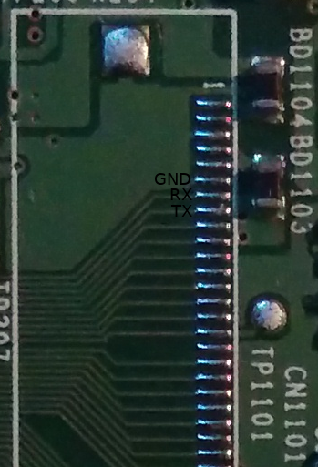
After a couple of bug fixed I was able to look for the GPIOs: I used
my oscilloscope to touch each pin exposed on the PCB and finally
I find out the pinout of the UART
interface: it's located in the connector CN1101 with pin 6, 7, 8 as indicated in picture
Connecting to it with a baud of 115200 I was greeted with the following bootlog
LED Driver init.
TSADC init.
MAX8903A: DC Input.
MAX8903:DC = 1
␛[1;34m DC Input Mode! ␛[0m
NAND: V7018
[NAND        ] [PORT CONFIG - CS[0, 1] [NAND Data Port: GPIO_B Hw4 ~ Hw11]
[NAND        ] [BClk 156MHZ][1Tick 65][RE-S:0,P:7,H:4][WR-S:0,P:5,H:4][COM-S:2,P:15,H:15]
[NAND        ] [NB Area:4MB][DT Area:931MB][HD Area0:9MB][HD Area1:9MB]

=============================================
    tcboot ver 0.5 for TCC8900 Linux
    Board ver TCC8900_WINCE_LINUX_DEMO
    DATE:Jul 12 2010, TIME:13:11:27
=============================================
CHIP ID: 0x0000000E0DD3C3B0
CLOCK: PLL0:540, PLL1:560, PLL2:468, PLL3:528, CPU:506, BUS:280
       DDI:264, GRP:0, IOB:156, VBUS:0, VPU:0, SMU:117
LCD: Post Parallel Device Initialize..
DLP260X_Done Wait count = 1 msec
emu_done reset = 0x1, ret = 0x1
MAX8903A DC input =1
DPP260X Initialize Success!
DLP : 854X480 RGB888 Mode
DPP260X Current Red=0x32A,Green=0x32A,Blue=0x32A
FWDN: checking...
Loading...
length = 0x67C000, CRC = 0xFC025306
Load Ok! Jump to 0x40300000 (0xEA000016)

Linux version 2.6.28 (phking@linux-hth0) (gcc version 4.3.2 (Sourcery G++ Lite 2008q3-72) ) #3 Mon Jul 12 13:28:17 KST 2010
CPU: ARMv6-compatible processor [410fb766] revision 6 (ARMv7), cr=00c5387f
CPU: VIPT nonaliasing data cache, VIPT nonaliasing instruction cache
Machine: Samsung Oberon Board
Warning: bad configuration page, trying to continue
Memory policy: ECC disabled, Data cache writeback
create_mapping:0x40200000->0xc0000000(0x5000000)
create_mapping:0x402a9000->0xffff0000(0x1000)
create_mapping:0xf0000>0xf0000000(0x100000)
create_mapping:0xf0100000->0xf0100000(0x100000)
create_mapping:0xf0200000->0xf0200000(0x100000)
create_mapping:0xf0300000->0xf0300000(0x100000)
create_mapping:0xf0400000->0xf0400000(0x100000)
create_mapping:0xf0500000->0xf050000000000)
create_mapping:0xf0600000->0xf0600000(0x100000)
create_mapping:0xf0700000->0xf0700000(0x100000)
create_mapping:0x10000000->0xeff00000(0x100000)
Serial Number: 0000000e0dd3c3b0
Built 1 zonelists in Zone order, mobility grouping on.  Total pages20
Kernel command line: console=ttySAC0 lpj=2523136 initcall_debug=0   mem=80M
tcc8900_irq_init
PID hash table entries: 512 (order: 9, 2048 bytes)
 ### CORE CLOCK (506250000 Hz), BUS CLOCK (280000000 Hz) ###
Console: colour dummy device 80x30
console [ttySAC0] enabled
Dentry cache hash table entries: 16384 (ord4, 65536 bytes)
Inode-cache hash table entries: 8192 (order: 3, 32768 bytes)
_etext:0xc0762000, _text:0xc04f5000, _end:0xc07a5db8, __data_start:0xc0762000, __init_end:0xc04f5000, __init_begin:0xc0100000
Memory: 80MB = 80MB total
Memory: 74240KB available (2484K code, 271K data, 4052K init)
Calibrating delay loop (skipped) preset value.. 504.62 BogoMIPS (lpj=2523136)
Mount-cache hash table entries: 512
CPU: Testing write buffer coherency: ok
net_namespace: 288 bytes
NET: Registered protocol family 16
attached TCC adc driver
SCSI subsystem initialized
usbcore: registered new interface driver usbfs
usbcore: registered new interface driver hub
usbcore: registered new device driver usb
NET: Registered protocol family 2
IP route cache hash table entries: 1024 (order: 0, 4096 bytes)
TCP established hash table entries: 4096 (order: 3, 32768 bytes)
TCP bind hash table entries: 4096 (order: 2, 16384 bytes)
TCP: Hash tables configured (established 4096 bind 4096)
TCP reno registered
NET: Registered protocol family 1
Telechips Dynamic Power Management.
NetWinder Floating Point Emulator V0.97 (double precision)
fuse init (API version 7.10)
msgmni has been set to 145
Block layer SCSI generic (bsg) driver version 0.4 loaded (major 253)
io scheduler noop registered
io scheduler cfq registered (default)
i2c /dev entries driver
tcc-i2c tcc-i2c: i2c-0: I2C adapter
cs42l52_i2c_probe:
fb[0]::map_video_memory: dma=45200000 cpu=c6000000 size=00800000
fb0: tccfb frame buffer device
fb[1]::map_video_memory: dma=45a00000 cpu=c7000000 size=00400000
fb1: tccfb frame buffer device
fb[2]::map_video_memory: dma=45e00000 cpu=c7800000 size=00400000
fb2: tccfb frame buffer device
tcc proc filesystem initialised
OBERON_PWR Driver
oberon_p5v_control: onoff = 1
Obenron MAX8903A Driver
Battery Voltage = 0.4
MAX8903A: DC Connected!
Obenron TW8816 Driver
tcc_intr: init (ver 2.1)
tcc_pwm: init (ver 0.1)
Obenron DPP260x Driver
DPP260X Check ID Success!..
Obenron TCC_WDT Driver
OBERON_MEM Driver
Obenron OBERON_LEDS Driver
TimerX init(TX-Timer0).
tcc8900-uart.0: tcc-uart0 at MMIO 0xf0532000 (irq = tcc8900-uart.1: tcc-uart1 at MMIO 0xf0532100 (irq = loop: module loaded
TRACE: DPM is now installed
Driver 'sd' needs updating - please use bus_type methods
Initializing USB Mass Storage driver...
usbcore: registered new interface driver usb-storage
USB Mass Storage support registered.
dwc_otg: version 2.60a 22-NOV-2006
DWC_otg: Internal DMA Mode...
DWC_otg: Dedicated Tx FIFOs mode
DWC_otg: Using DMA mode
dwc_otg dwc_otg.0: DWC OTG Controller
dwc_otg dwc_otg.0: new USB bus registered, assigned bus number 1
dwc_otg dwc_otg.0: irq 48, io mem 0x00000000
DWC_otg: Init: Port Power? op_state=1
DWC_otg: Init: Power Port (0)
usb usb1: configuration #1 chosen from 1 choice
hub 1-0:1.0: USB hub found
hub 1-0:1.0: 1 port detected
mice: PS/2 mouse device common for all mice
Oberon GPIO Keypad Driver...
input: Oberon keypad as /class/input/input0
TCC RTC, (c) 2009, Telechips
tcc-rtc tcc-rtc: rtc core: registered tcc-rtc as rtc0
tcc-sdhc1: init
Set ID to device mode
Advanced Linux Sound Architecture Driver Version 1.0.18rc3.
ASoC version 0.13.2
TCC89XX  cs42l52 ALSA SoC driver ver1.1 10/2008
asoc: CS42L52 <-> tcc-i2s mapping ok
CS42L52: Cirrus CS42L52 codec , revision 3
soc_cs42l52_write: Can't set Limiter
ID change ISR : Device
DWC_otg: Internal DMA Mode...
soc_cs42l52_setup: <Mono Speaker out>.
DWC_otg: USB RESET
CS42L52: Cirrus Logic ALSA SoC codec cs42l52 driver verison 1.1 10/2008
ALSA device list:
  #0: TCC89XX (CS42L52)
TCP cubic registered
NET: Registered protocol family 17
VFP support v0.3: implementor 41 architecture 1 part 20 variant b rev 5
tcc-rtc tcc-rtc: hctosys: invalid date/time
DWC_otg: Internal DMA Mode...
hp_detect_work:  SPK Sound
oberon_volume = 0, highlow=1
init started:  BusyBox v1.4.2 (2010-05-20 22:17:07 KST) multi-call binary
Starting pid 352, console /dev/console: '/etc/init.d/rcS'
run /etc/init.d/rcS
mdev init: ...
TCC8900_nand: module license 'Proprietary. (C) 2008 Telechips Inc.' taints kernel.
Dumy-Ready Interrupt-!!!!!!!!!!!!!!!!
[NAND        ] [PORT CONFIG - CS[0, 1] [NAND Data Port: GPIO_B Hw4 ~ Hw11]
[NAND        ] [BClk 156MHZ][1Tick 65][RE-S:0,P:7,H:4][WR-S:0,P:6,H:4][COM-S:2,P:15,H:15]
[NAND        ] [NB Area:4MB][DT Area:931MB][HD Area0:9MB][HD Area1:9MB]
 ndda: ndda1 ndda2 ndda3
[tcc_nand] init ndd(TCC8900, V7018)
[tcc-gadget]fsg_init start
[tcc-gadget]fsg_bind start
fsg_bind: gadget->name = dwc_otg_pcd
usb_gadget_controller_number: gadget->name = dwc_otg_pcd
g_file_storage gadget: File-backed Storage Gadget, version: 7 August 2007
g_file_storage gadget: Number of LUNs=1
[tcc-gadget]fsg init end
pwd = /
OBERON Update Script(pre)....
[Update File Check] Update Files Not Exist...
dosfsck_check pwd=/
[/usr/sbin/dosfsck] /dev/ndda1 .. ok
dosfsck_check pwd=/
[/usr/sbin/dosfsck] /dev/ndda2 .. ok
dosfsck_check pwd=/
[/usr/sbin/dosfsck] /dev/ndda3 .. ok
Starting pid 427, console /dev/ttySAC0: '/bin/sh'
/ #
and finally the shell. To my surprise the problem was that the user partition
was empty, so simply untarring the update file into the root of the filesystem
fixed the problem my friend had. Fortunately it is possible to insert a SD card
with the update in it into the device and see it mounted in /media
otherwise I would had to upload it using the serial with a
my script
(but it is very slow).
This wraps up this post: at end I'm very happy of what I obtained and there is space for further work on this device:
- dump of the boot
ROM - complete the mapping of the pins creating a plugin for sigrok that can decode what GPIO is
- write an application to update the firmware directly using the
FWDNprotocol (here some notes about that).
If you interested I have a repository with this and a couple of other devices that I analyzed during the years.
Comments
Comments powered by Disqus