Reusing old shit: laptop keyboard
Here we are with another experiment in reusing otherwise trash-destined electronics material; in this episode we are going to refurbish a keyboard, from the recovering of the internal "matrix" to the design of the PCB destined as the controller board, to finally reworking of an existing firmware to create a new USB keyboard.
The keyboard under recovery is the following
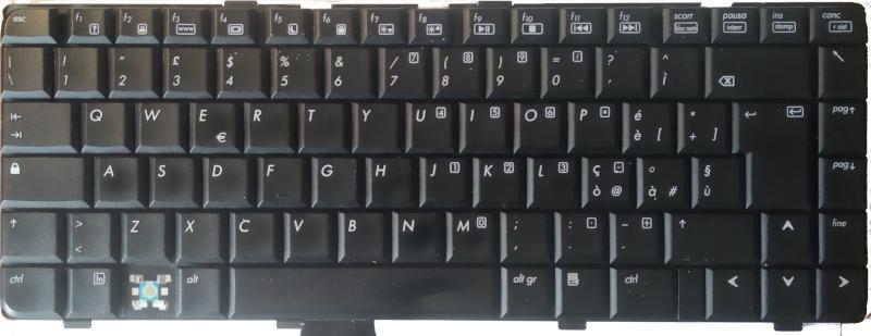
extracted from an HP pavillon, model AT8A. It has a ribbon cable with 26 pins and pitch of 1.0mm.
Matrix recovery
The underlying working of a keyboard is described by a matrix of nodes corresponding to each key; a set of signals act as inputs (for convention I identify them as the rows of the matix) and the remaining as outputs (columns): when a key is pressed the corresponding couple of input/output lines (row/column) are connected allowing to detect the event.
The algorithm used to implement in hardware the mechanism just described
is to start with all the input lines with the same logic level and then change
only one input signal at the time, with the remaining unaltered. For each input the
output lines are checked for changes and if this happens this means that a key is pressed.
When all the input signals
have been acted upon the algorithm use the row/column couple to understand the
key pressed and translates that in keyboard scancodes to send via USB.
The first step to reuse the keyboard is to recostruct the internal matrix using the algorithm described above: in order to do that I'm using the following program, in this case I'm using the Arduino Mega because of the big number of available pins: I'm using a breakout board as adapter to connect the FPC cable to the pins 22-51 of the Arduino·
/*
 * KEYBOARD MATRIX RECOVERY
 * ------------------------
 *
 * Press a key in you keyboard and see which connections are activated.
 *
 * Since we cannot read reliably without using pull up we need
 * to set one pin to output LOW and the other to input with a
 * pull up enabled. In this way when the key is pressed the input
 * should read low.
 *
 * Originally designed for the Arduino Mega.
 *
 */

bool just_started = true; // check that there is not key pressed when the app starts

#define N_PINS(_p) (sizeof(_p)/sizeof(_p[0]))
/*
 * The connector I'm using has 30 pins, modify as needed.
 *
 * NOTE: some combinations result in a match always, so it's
 * needed a mechanism to blacklist them
 */
unsigned int pins[] {
  22, 23, 24, 25, 26, 27, 28, 29, 30, 31,
  32, 33, 34, 35, 36, 37, 38, 39, 40, 41,
  42, 43, 44, 45, 46, 47, 48, 49, 50, 51,
};

// TODO: use this to create the complete matrix
char* layout[88] = {
  "KEY_ESC", "KEY_F1", "KEY_F2", "KEY_F3", "KEY_F4", "KEY_F5", "KEY_F6", "KEY_F7", "KEY_F8", "KEY_F9", "KEY_F10", "KEY_F11", "KEY_F12", "KEY_SCROLLLOCK", "KEY_PAUSE", "KEY_INSERT", "KEY_DELETE",
  "KEY_BACKSLASH", "KEY_1", "KEY_2", "KEY_3", "KEY_4", "KEY_5", "KEY_6", "KEY_7", "KEY_8", "KEY_9", "KEY_0", "KEY_APOSTROPHE", "KEY_IT_IGRAVE", "KEY_BACKSPACE", "KEY_HOME",
  "KEY_TAB", "KEY_Q", "KEY_W", "KEY_E", "KEY_R", "KEY_T", "KEY_Y", "KEY_U", "KEY_I", "KEY_O", "KEY_P", "KEY_IT_EGRAVE", "KEY_PLUS", "KEY_RETURN", "KEY_PAGEUP",
  "KEY_CAPSLOCK", "KEY_A", "KEY_S", "KEY_D", "KEY_F", "KEY_G", "KEY_H", "KEY_J", "KEY_K", "KEY_L", "KEY_IT_OGRAVE", "KEY_IT_AGRAVE", "KEY_IT_UGRAVE", "KEY_PAGEDOWN",
  "KEY_MOD_LSHIFT", "KEY_IT_TRIANGLE", "KEY_Z", "KEY_X", "KEY_C", "KEY_V", "KEY_B", "KEY_N", "KEY_M", "KEY_COMMA", "KEY_DOT", "KEY_MINUS", "KEY_MOD_RSHIFT", "KEY_UP", "KEY_END",
  "KEY_MOD_LCTRL", "KEY_MOD_LMETA", "KEY_MOD_LALT", "KEY_SPACEBAR", "KEY_MOD_RALT", "KEY_BOH", "KEY_MOD_RCTRL", "KEY_LEFT", "KEY_DOWN", "KEY_RIGHT"
};


struct _signals {
  unsigned int lines[2];
  bool was_activated;
  bool activated;
} signals;


/*
 * Here we setup only the serial.
 */
void setup() {
  Serial.begin(115200);
  Serial.println(" --[Start keyboard matrix recovery ]--");
}


void set_input(unsigned int pinInputIndex)  {
  pinMode(pins[pinInputIndex], OUTPUT);
  digitalWrite(pins[pinInputIndex], LOW);
}

void set_outputs(unsigned int pinInputIndex) {
  unsigned int cycle;
  for (cycle = 0 ; cycle < N_PINS(pins) ; cycle++) {
    if (cycle == pinInputIndex) {
      continue;
    }
    // here we need the pullup otherwise the reading will be floating
    pinMode(pins[cycle], INPUT_PULLUP);
  }
}

void look_for_signal(unsigned int inputPinIndex) {
  unsigned int cycle;
  for (cycle = 0; cycle < N_PINS(pins) ; cycle++) {
    if (inputPinIndex == cycle)
      continue;

    unsigned value = digitalRead(pins[cycle]);
    if (value == LOW) {// since we are using pull ups from the input side we need to look for LOW level
      signals.lines[0] = inputPinIndex;
      signals.lines[1] = cycle;
      signals.activated = true;

      if (just_started) {
        Serial.print(" BLACKLIST PLEASE ");
      }
      communicate_signal();
    } else { just_started = false;}
  }
}


void try_combination(unsigned int inputPinIndex) {
  set_input(inputPinIndex);
  set_outputs(inputPinIndex);

  look_for_signal(inputPinIndex);
}

/*
 * output the activated lines as a tuple.
 */
void communicate_signal() {
  // output a key only if the signal is activated now but not the previous time
  if (!(signals.activated && !signals.was_activated))
    return;
  Serial.print("(");
  Serial.print(signals.lines[0], DEC);
  Serial.print(", ");
  Serial.print(signals.lines[1], DEC);
  Serial.println("),");
}

/*
 * Here we are looping over all the combination of input/output pairs to
 * find possibly connections.
 */
void loop() {
  unsigned int inputPinIndex;

  signals.activated = false;


  for (inputPinIndex = 0 ; inputPinIndex < N_PINS(pins) ; inputPinIndex++) {
    try_combination(inputPinIndex);
  }

  //communicate_signal();

  signals.was_activated = signals.activated;
  signals.activated = false;
}
From pressing any key in order, I obtain the following array contaning all the couple of pins that each key triggers (reworked to be used directly in python)
>>> keys = [tuple(sorted(_)) for _ in keys]
>>> keys = [
  (25,15), (14,13), (17,13), (18,13), (25,13), (17,16), (18,16), (25,16), (16,14), (17, 4), (18, 4), (25, 4), (14, 4), (25, 9), (14, 5), (25, 2), (14, 2),
  (17,15), (23,15), (23,16), (23,13), (23,12), (17,12), (17,10), (23,10), (23, 9), (23, 4), (23, 3), (17, 3), (14, 3), (25, 5), (18, 2),
  (18,15), (24,15), (24,16), (24,13), (24,12), (18,12), (18,10), (24,10), (24, 9), (24, 4), (24, 3), (18, 3), (18, 9), (21, 5), (17, 2),
  (15,14), (21,15), (21,16), (21,13), (21,12), (25,12), (25,10), (21,10), (21, 9), (21, 4), (21, 3), (25, 3), (17, 5), (21, 2),
  (22,20), (17, 9), (20,15), (20,16), (20,13), (20,12), (14,12), (14,10), (20,10), (20, 9), (20, 4), (20, 3), (24,22), (24, 5), (20, 2),
  (19,18), (17,11), (25, 8), (23, 6), (20, 5), (14, 6), (17, 7), (21,19), (24, 2), (23, 5), (23, 2),
]
I created simple macro to massage the data
>>> get = lambda x: set([_ for _ in keys if _[1] == x or _[0] == x])
so to have the list of how many nodes each key determines:
>>> combinations = [(_, len(get(_))) for _ in range(30)]
>>> combinations
[(0, 11),
 (1, 11),
 (2, 11),
 (3, 2),
 (4, 11),
 (5, 11),
 (6, 2),
 (7, 10),
 (8, 12),
 (9, 8),
 (10, 8),
 (11, 10),
 (12, 8),
 (13, 8),
 (14, 1),
 (15, 8),
 (16, 7),
 (17, 1),
 (18, 1),
 (19, 2),
 (20, 7),
 (21, 8),
 (22, 8),
 (23, 8),
 (24, 0),
 (25, 0),
 (26, 0),
 (27, 0),
 (28, 0),
 (29, 0)]
>>> len([line for line, count in combinations if count != 0])
24
Since I'm looking for "round numbers" it's interesting to see that a couple of signals are linked to 8 others, but the real pro-gamer move is looking for signals that have more than eight relations:
>>> inputs = set([line for line, count in combinations if count > 8])
>>> inputs
{0, 1, 2, 4, 5, 7, 8, 11}
>>> unused = set([line for line, count in combinations if count == 0])
>>> total = set(range(30))
>>> outputs = total - inputs - unused
>>> len(outputs)
16
>>> outputs
{3, 6, 9, 10, 12, 13, 14, 15, 16, 17, 18, 19, 20, 21, 22, 23}
>>> inputs & outputs
set()
after analyzing I can split the matrix with the following scheme of 8 inputs and 16 outputs
| Rows | 0 | 1 | 2 | 4 | 5 | 7 | 8 | 11 | ||||||||
| Columns | 3 | 6 | 9 | 10 | 12 | 13 | 14 | 15 | 16 | 17 | 18 | 19 | 20 | 21 | 22 | 23 |
NOTE: although there are \(8*16 = 128\) possible keys, only 87 are used, so some signals are underused.
Controller board design and firmware
Since my intention is to use the ATMega32U4 (the main advantage is the builtin
USB and my experience with it) I need to find a way to minimize pins usage: 24 pins are not available in
this chip so I decideded to use 8 pins for the inputs, in particular the bank
identified with PORTD so to access them with a single register (in this chip
only PORTD and PORTB are "complete" and PORTB will be used for the
SPI communication); the remaining 16, the output pins, will be handled
via two daisy-chained shift registers (the 74HC165)
communicating via SPI protocol.
The pinout of the shift register is the following

where the signals are defined in the following way
| Signal | Description |
|---|---|
Vcc |
positive power supply (up to 6V) |
GND |
negative rail |
SH/~LD |
Shift/Load |
CLK |
clock for the shifting |
CLK INH |
must be tied low to enable clock |
Q_H |
serial output |
SER |
serial input |
Dx |
paraller inputs |
Here below a copy of the timing diagram from the datasheet

TL;DR: the \(SH/\overline{LD}\) determines if the chip is in the load or shift state; in the first case the internal state of the shift register is set from the values present at the signals \(Dx\), instead for the other case (with also the condition of \(CLK INH\) being low) the internal state is shifted "outside" one bit at the time via the signal \(Q_H\). The \(SER\) signal can be used to concatenate shift registers together. As you can see from the timing diagram the most significant bits are shifted first.
Reading the ATMega32U4's
datasheet
at section 17, and the application note
AVR151: Setup and Use of the SPI,
I have all the information needed to interact with the SPI subsystem, in
particular the pins needed are the following
| Signal | pin | Description |
|---|---|---|
SS |
PB0 |
chip select |
SCK |
PB1 |
clock |
MOSI |
PB2 |
Master Output Slave Input |
MISO |
PB3 |
Master Input Slave Output |
For my use case the MOSI is not necessary since we are not going to communicate
data to the shift register but I don't think is possible to reuse anyway. For
latching the data on the shift registers the SS signal is used.
This below is the schematics of the board (it's an SVG file so you can zoom as
much as you want)

I'll complete the post once that I'll send the board to manifacture and I tested it.
For the firmware I re-used the code from kmani314/ATMega32u4-HID-Keyboard
reworking the matrix-related code to use SPI as described above; the final code
with the board files are in my fork at
gipi/ATMega32u4-HID-Keyboard.
There isn't very much to say about it, I think it's a pretty standard code to
implement a USB device. The only thing worth mentioning is the
script
to generate the layout header file from the output of the script at the start of
the post. This saves you a lot of typing and maybe in the future I can think of
automatize all the process a little more :)
Comments
Comments powered by Disqus