Updating my Anet A8 to the newest Marlin firmware
How you already know, I own a cheap 3d printer that is an Anet A8, a simple clone of a Prusa Mk2, that I use to, you know, 3d print stuffs. In the near future I would like to modify it and make it a little milling machine or a laser engraver and in order to do that I need to find some extra pins to drive these devices.
By the way, in order to have these functionalities I need to activate it recompiling the firmware, and since the original firmware obtained with the printer is pretty outdated I tought to use the original Marlin firmware so to have bug fixes and new functionalities.
Porting
First of all we need the source code: this is available at the github repo
$ git clone
$ cd Marlin
$ git checkout --track origin/1.1.x
if you want you can create a branch for your printer.
Now I can compare the options between the original firmware and the default settings; there is a configuration guide on the firmware home site with step to step instructions, in this post I will document the more important options and some advices.
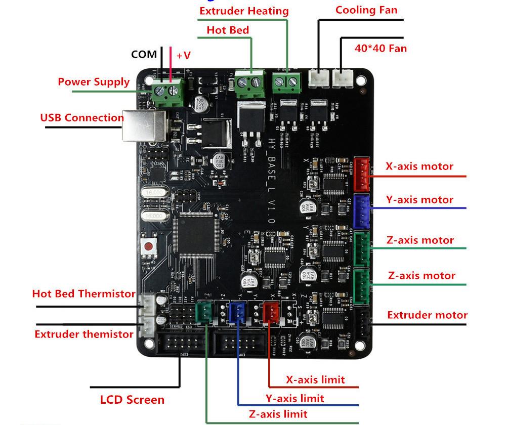
First off all you need to know what kind of board you have, in my case I have a RAMPS 1.3, (or maybe RAMP 1.4 it's not very clear the distiction, from what I see the only things changing are the extra pins but check your case).
However it has one extruder, one bed and one fan; the code associated with that in the original firmware
is 33 that corresponds to BOARD_RAMPS_13_EFB in Marlin.
After that I checked the pins definition in Marlin/pins_RAMPS.h for differences
I started to enable features: my printer has a display that is possible to enable with
REPRAP_DISCOUNT_SMART_CONTROLLER and also a SD Card, enabled with SDSUPPORT.
Now I arrive to the settings that are dangerous, in the sense that can damage your printer if you set it wrong: until you are sure all is working right, stay very near to the printer with a finger on the power switch, in particular if you have intention to move the head, calling the home procedure for example.
The first important options are related to the endstops:
X_MIN_ENDSTOP_INVERTINGY_MIN_ENDSTOP_INVERTINGZ_MIN_ENDSTOP_INVERTING
that in my case were not correct: the default configuration for my printer caused it to think that the head was always triggering the endstops.
To check that use the M119 code, if you see TRIGGERED as in the example below
anet> query M119
Reporting endstop status
x_min: TRIGGERED
y_min: TRIGGERED
z_min: TRIGGERED
ok
probably means that you have to check this options.
Another option that was inverted was that for the direction of the motor of the extruder, i.e.
INVERT_E0_DIR: in my situation, after waiting a few minutes, I have seen the filament unloading itself.
Another very important setting is the DEFAULT_AXIS_STEPS_PER_UNIT that indicates
how many steps for unit of measurement the stepper motors have to move: in my case it was
very different from the right values, in particular the z axis had ten times the correct value (indeed when tested the first
time the high speed of it had raised attention from my part).
There are other options less dangerous but important for a good print quality
DEFAULT_MAX_FEEDRATE-
DEFAULT_XJERK,DEFAULT_YJERKandDEFAULT_ZJERK HOMING_FEEDRATE_XYHOMING_FEEDRATE_Z
I have copied it from the original firmware, in case you don't have any, look at some example configurations present in the Marlin source tree.
Finally some options that are new with respect to the original firmware: these are options
involving thermal protection;
the THERMAL_PROTECTION_HOTENDS and THERMAL_PROTECTION_BED and the related
options: in my case, when the fan started spinning, the extruder temperature
was dropping of ten degrees and it was unable to make it raise fast enough
and printer was halting to prevent temperature runaway; increasing the acceptable
temperature difference and/or the time allowed to balance it, fixed the problem.
Disabling them it's not a viable option since you will risk to put your house in fire if the thermostat detaches from the printing head.
Bed calibration
When all the important options are in place, it's a good occasion to fix the placement of the bed as seen from the firmware: there are some calibration print (remember to print without build adesion).
At first didn't seemed a so important step but, bad enough, the informations I have found were not clear so I'll try here to summarize a quick way to fix the printable area configuration.
The problem starts since normally the endstops don't place the printer head at the origin of
the printable bed, there are some possible options to fix that, my approach is to
fix all in the firmware avoiding the use of the eeprom to save the settings
(if you want to use that way the M206 command enabled via EEPROM_SETTINGS
is your friend).
A little digression: after a quick reading of the Marlin's source code seems that there are two kinds of coordinates system: one native and one logical that are converted one into another using some macro magic like
#define NATIVE_TO_LOGICAL(POS, AXIS) ((POS) + WORKSPACE_OFFSET(AXIS))
#define LOGICAL_TO_NATIVE(POS, AXIS) ((POS) - WORKSPACE_OFFSET(AXIS))
that are only enabled if is allowed to have a workspace offset (reading the code is pretty
simple understand what's going on). Long story short: when you issue the G28 command (i.e. auto home, where endstops are)
the native coordinate system set its origin; you with the following defines set the allowed movements
in the logical coordinate system
#define X_MIN_POS -10
#define Y_MIN_POS -15
#define X_MAX_POS X_BED_SIZE
#define Y_MAX_POS Y_BED_SIZE
#define Z_MAX_POS 200
#define Z_MIN_POS 0
instead you can set where the home is in the native coordinates system
#define MANUAL_X_HOME_POS -10
#define MANUAL_Y_HOME_POS -15
#define MANUAL_Z_HOME_POS 0
you can notice the negative values: they are the location in the original coordinate system of the origin of the printable area of the bed; now you have to set explicitely that in the original coordinate system
In practice you can move the head using the command G0 until you find the right position of the head;
when you have set all the necessary you can check the final result using the command M211
that summarizes the configuration obtained
anet> query M211
echo:Soft endstops: On   Min: X-10.00 Y-15.00 Z0.00  Max: X200.00 Y200.00 Z200.00
ok
Now you have to set your slicer to choice to follow these settings without extra steps.
At the end obviously the main way to test all is correct is to test some calibration cube.
Find free pins
Looking at the GCODE you can see that exist some codes that allow to handle pins: - M 42 Set Pin State - M 43 Debug Pins - M 43 T Toggle
you need to activate these functionalities using PINS_DEBUGGING when compiling.
The other adventure will be find out which pins exposed free on the board are which
My board has like four usable extra pins near the stepper motor ones, named
A11, A12, D11 and D12; each one is placed in a column with another two
pins, GND (in the middle) and 5V (the lower one).
With my exceptional detective ability I think to have learnt that D stays for digital
and A for analogic; in my printer there is the following mapping between external output pins
of the board and the ATmega
| Board pin | ATmega pin |
|---|---|
| D11 | 11 |
| A11 | 65 |
| A12 | 66 |
Bad enough, it seems that the only pin pwm-capable is the number 11 but is used for internal timing in the firmware: indeed if I try to use it I obtain the following error:
In file included from sketch/MarlinConfig.h:40:0,
                 from /opt/Marlin/Marlin/Marlin.ino:31:
SanityCheck.h:1547: error: #error "Counter/Timer for SPINDLE_LASER_PWM_PIN is used by a system interrupt."
       #error "Counter/Timer for SPINDLE_LASER_PWM_PIN is used by a system interrupt."
If I want to use PWM probably the only option is to re-purpose a fan connector. I'll see.
Comments
Comments powered by Disqus