PS/2 protocol
In this post I will experiment with the PS/2 protocol.
If you want view live experimenting with it look this video from Ben Eater where he builds a receiver.
The PS/2 physical interface is implemented with 4 wires (the connector can have more but unused)
that are
VCCGNDDATACLK
The wires of interest here are DATA and CLK obviously: are two data lines that
are usually implemented with an open collector circuit with a pullup resistor. The
logic level is 5V with DATA and CLK pulled high when idle. I found out that
an original PS/2 keyboard works just fine with 3V3.
The board connector (of type Mini-DIN-6) has the following pinout (courtesy of wikipedia)
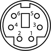
- 1:
DATA - 2: not connected
- 3:
GND - 4:
VCC - 5:
CLK - 6: not connected
The protocol can be described saying that the data is transmitted as packet of 11 bits
so composed: one start bit with logic level 0, then 8 bits with the keycode of the
keyboard, with the LSB trasmitted first; the data is terminated with the parity bit
and the stop bit always logic 1. The host must sample the DATA line at the
failing edge of the CLK line. Both clock and data signals are logic level high when inactive.
The protocol allows a communication also from the host to the keyboard by pulling low the CLK
line by the host: this disables the communication from the keyboard.
This is a legacy protocol, widely used more than 10 years ago to connect
mouse and keyboard to desktop that now are superated by devices using the USB protocol.
It's very rare to observe in the wild such technology but lucky for us, each USB keyboard
is capable to emulate a PS/2 one, simply use
D- as DATA and D+ as CLK line.
The screen capture just below shows the two signal lines (CLK is the signal in the upper part and DATA
the other) as recorded by my oscilloscope: I pressed the a key of the keyboard
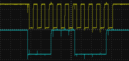
if you sample the DATA signal at the failing edge of the CLK line you obtain the following values
0 | 0 0 1 1 1 0 0 0 | 0 1
that correspond to the 1C hexdecimal value (binary 00011100).
FPGA
TODO: build a receiver in verilog
Comments
Comments powered by Disqus